


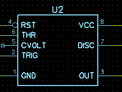
@gunrunnerjohn posted:The pin numbers are correct, it's common for schematic representations of parts not to have the pin layouts exactly like the physical part. When I call up a 555 chip in DipTrace schematic capture, I get this:
Clearly, that's not how the pins are arranged on the chip. A vast majority of the IC's are this way in schematic capture applications.
The part I wondered about on the dual flasher is the polarity of the LED's. How can LED2 be correct, the cathode is clearly facing the most positive part of the circuit.
I suspect that part should be reversed for proper operation.

I am just wondering if anyone built this circuit to see if it works, I've built a couple that were posted on line only to find they don't work.
Ray
