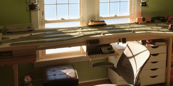
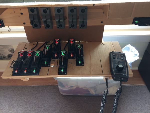
And now a word about control(s). As my interest in Operation grew and the track-plan evolved so did controls. The PER started out with a variant of the familiar central control panel.
Mine looked like this:
An MTH Z-1000 Throttle, track switch remote controls and uncoupler remote controls. The first move away from centralized control was a walk-around throttle:
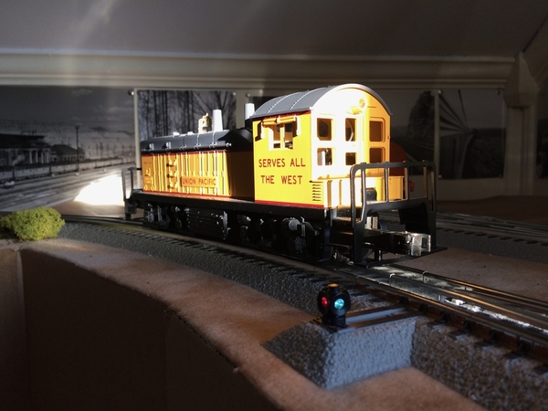
Then a big change came to the PER. Motive power had been a Lionel PWC NW2:
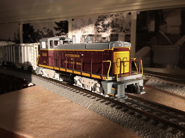
But then the PER tested an MTH PS3 SW1500 and I was smitten by Speed Control:
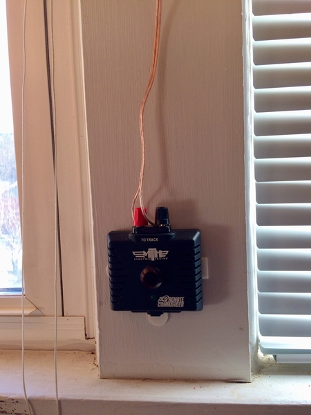
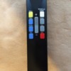
Slow speed switching moves suddenly became a reality! Then I discovered DCS. My original interest was because using DCS gives access to the 100-step throttle which provides even better slow-speed control. But as well, DCS provides a walk-around throttle. I chose to use the Remote Commander, a simple inexpensive throttle consisting of a hand-held IR Remote (like a TV) :
and a Receiver which picks up the IR commands and produces the necessary DCS signal to the tracks:
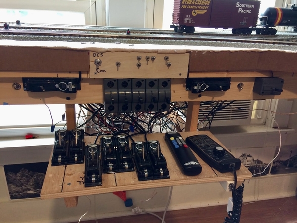
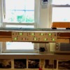
Here is the hybrid control panel that resulted with both DCS and Conventional Walk-around. Also seen in this pic are car-stopper controls which by then I had invented:
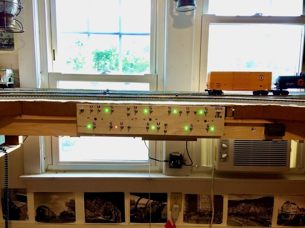
The next iteration usied all miniature toggle switches and dropped Conventional control:
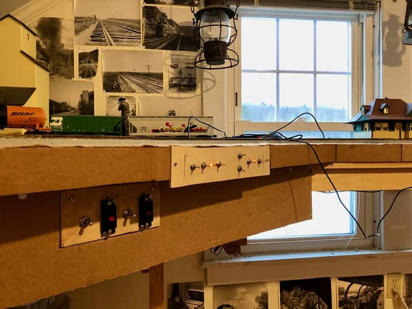
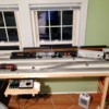
Putting it all together; with slow-speed switching, uncoupling and coupling I found that I really wanted to get right up close to the action so I went total walk-around with de-CTC (no central control panel at all). And that is where we are today:
A few details wrt wiring now.
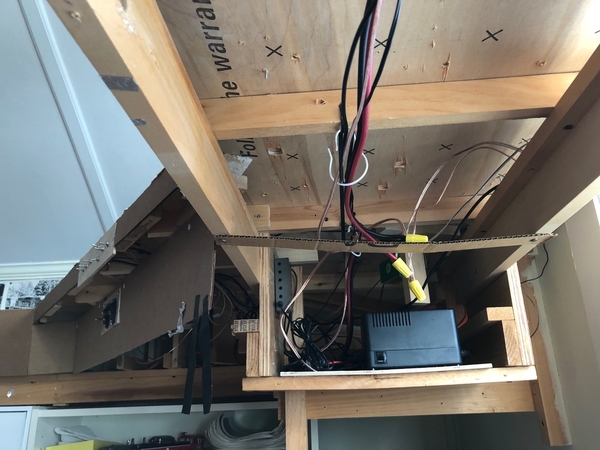
First, a pic of the underside of the PER illustrating a benefit of using DCS and of de-centralized control:
Layout wiring consists pretty much of three buss wires, a 12ga common, a 12ga track power buss and a doubled 18ga accessory buss. Short wire runs connect mini-panels to the track switches, remote uncouplers and car-stoppers they control. And that is it.
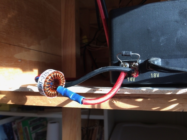
Since the PER runs equipment with lots of electronics (PS3 under DCS) TVS Diodes are a must to provide Transient Voltage Suppression. A TVS is installed across the transformer output terminals:
Also in this pic is a 22uH toroid-wound inductor in series with track power. This is necessary when using a DCS Remote Commander in passive mode.
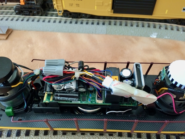
Most important though is a TVS Diode inside each locomotive wired directly across the track power and ground inputs to the PS3 board:


