@gunrunnerjohn posted:Cool, I was wondering what the feedback loop was supposed to do, it's all really clear now. Very clever, I wonder if the guys at NJ-HR can use something like this. I see Bob is very attentively tuned in, perhaps you could share the exact part numbers and the code you used?
We went through a few iterations so the various sections are broken out over a few different boards, one for the trimpot, and one for the detection circuitry.
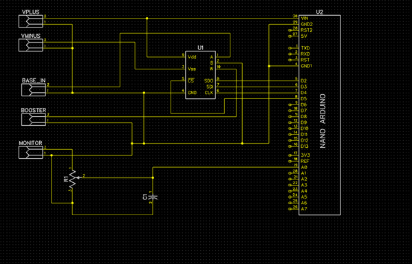
The gain stage we use off the pickup itself is this one: ZFL500LN which just runs off 15VDC. The digital trimpot was an AD5290YRMZ10. The control opamp isn't physical that was done on the microcontroller in software. We just used an arduino nano to read the level on the ADC and tune the trimpot until the ADC input matches a constant in the code (setpoint =120; )
Here's a screenshot of the trimpot Board in diptrace (schematic attached). This one is just the arduino with some connectors for the ADC input, some filtering some scaling and the trimpot itself.
Detector Board in diptrace (schematic attached). This is a differential envelope detector with a gain stage that goes into the arduino ADC port. Not much here except you need the nifty power supply module to get the +15/-15V for the opamp from a single supply input. The diodes are just 1n4148 signal diodes. I like the LM358N opamp since the input referred noise is low but you can go with whatever.
Honestly there's a billion ways you could implement this, and the above setup is probably not the best, it's just what we arrived after a few iterations.


