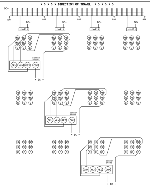
Perhaps you've got it all figured out or found a similar diagram, but if using the 3PDT contacts strictly for driving the LED signal heads:
For N signal heads on consecutive/adjoining blocks, you need N+1 relays. The leftmost relay can be a DPDT type. The rightmost relay can be a SPDT type. All relays in between are the 3PDT type. Or, use all 3PDT types and no need to make some connections on the leftmost and rightmost relays. Example above has 3 signal heads requiring 4 relays. I drew the wiring to each signal head separately to illustrate how the wiring "pattern" to each signal head simply repeats. If drawn all together it would look like a mess!
If you're messing around on the bench, you might look into placing a 25 cent resistor-capacitor filter on the DC relay coil contacts to demote chatter. That is, when a consist enters/exits a block, the lightweight wheel axles (e.g., pilot truck on a steam engine or trailing truck on a caboose) may make intermittent insulated-rail contact causing the LED signals to flicker. I'm pretty sure Dale covers this ... or I can elaborate if this is of interest.


