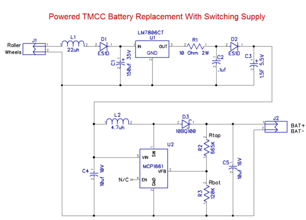
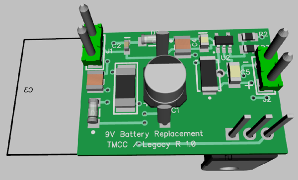
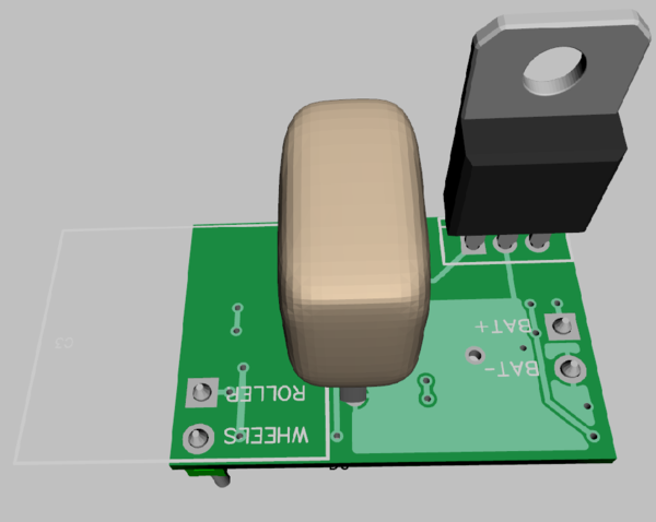
Here's a first cut at the configuration with the dual regulator design and a single SuperCap.
The large cap on the back would be the supercap, it folds away from the regulator and hangs out the side. You can see the outline of the supercap beyond the board footprint. The whole affair is about 1.6" long and less than an inch wide. Thickness will be around 5/8" to 3/4". The regulator folds over the PCB to reduce the size. The headers aren't actually installed, they're just holes in the PCB to solder wires to. The outputs would be soldered to a 9V battery connector, the input roller and wheels would be soldered to the track power. Polarity is important as the battery in TMCC locomotives shares it's negative with frame ground.


