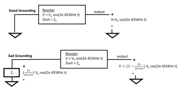
I'm talking about this grounding impedance. With the spectrum analyzer or even just time domain scope we see with some power strips or GFCIs we develop the voltage Zs/(Zs+Zo) x V between the ground terminal on the booster and the true building ground, where Zs is the series impedance added by the strip, booster or even just inductance off a long return wire.... Zo is the output impedance of the booster itself, and V is the output voltage of the booster V = Vo cos(wt) where w is 2 x pi x 455 KHz respectively.
Since the booster has finite output impedance Zo, and finite output Voltage V, that means that to satisfy KVL that any voltage being developed in the ground path scaled by Zs/(Zs+Zo) is coming directly off your output scaled by [1-Zs/(Zs-Zo)]. It's a loop so:
V[1-Zs/(Zo+Zs)] + V [Zs/(Zo+zs)] -V = 0 (KVL!)
Some of the dollar store terminal strips did really poorly... and that makes sense... the output Zo of the booster is a low number as it should be since it's intended to drive a rather large load (lots of capacitance), so even a low series resistance in the return path can have a pretty dramatic effect on the series combination Zs/(Zs+Zo)


