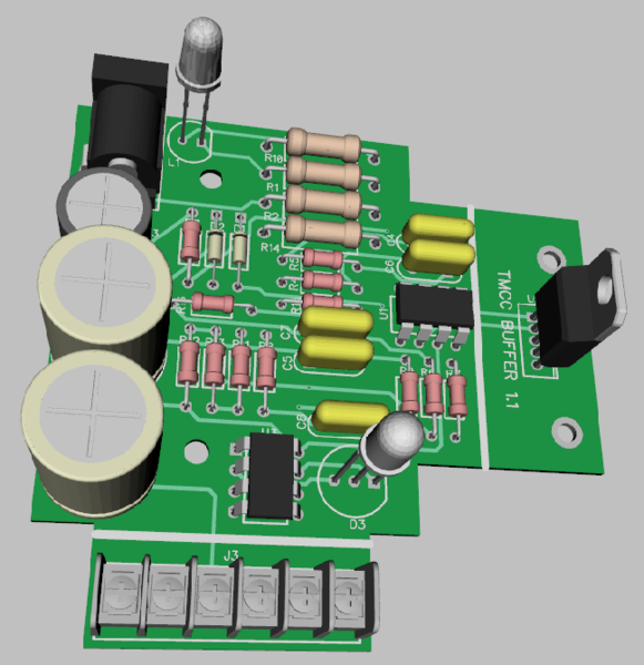
George, the booster will be in a small plastic enclosure about 4" x 2.5" x 1.5" tall. The buffer output amp heatsink will project out one end, and the six terminals for system connection will project out the side. The back side will have the plug for the 24V power brick. The top will have the two indicator LED's. This is the board that's inside the case, the heavy white lines denote where the board projects through the case.
There is no mounting provisions, however my advice is some sticky-back Velcro strips to attach it to the location of your choice. If you want to be able to see the power and signal level LED's, the top should be visible. Three of the terminal connections are required, earth ground, base input, and track output. The other three are provided for measurement of the input base and output track signal relative levels. They output a DC voltage that can be measured with any 1 meg-ohm or higher impedance meter (most digital meters). The earth ground will be tapped off the TMCC or Legacy power brick plug barrel with a male/female adapter that has a wire to attach to the buffer earth ground terminal.
I'd post a picture of the actual unit, but I don't have the prototype board in yet, I expect to have it before York, at least that's my plan.