


TMCC BUFFER PROGRESS REPORT
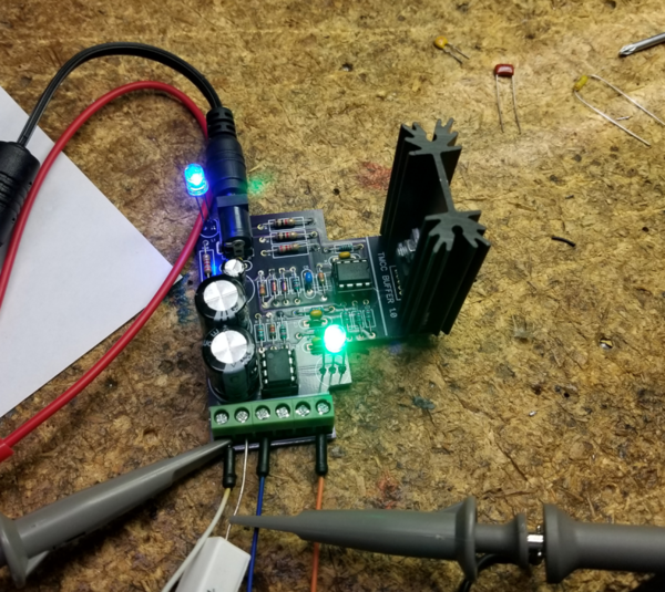
The prototype has been assembled, and the bench testing went well, looks like it works just like Dale's original. A 5V p-p signal in from my BASE1L yields a 15V p-p low-impedance signal out from the 3:1 power buffer driving a 50 ohm load. Testing with various capacitive loads is ongoing, but it's looking good. Extended running under load didn't cause any issues, the buffer appears to be loafing doing it's job.
Prototype TMCC Buffer on the bench. The blue LED is power, the green bi-color LED is indicating good signal strength. For a truly weak or no signal, the LED will be red. For a low amplitude signal, but still probably usable, the LED will be extinguished. I find that most old TMCC bases don't have the signal drive to light the LED, but the three Legacy bases and the BASE1L that I tested all had sufficient amplitude to light the green signal LED. You can also measure a DC voltage that is proportional to the amplitude of the input and output signals on the measurement terminals. In the final documentation I'll have a table that correlates the DC voltage to the p-p voltage of the signals so you can evaluate the signal levels without a 'scope.
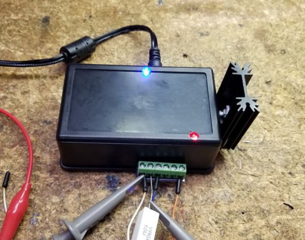
Prototype TMCC Buffer in enclosure, The power and signal strength LED's project through the top. There is no signal applied, and as you can see, the signal LED is red in this shot.
Right away I spotted one issue, I put the LED's too close to the edge of the board and they don't come through in the recessed section of the top. I also had to trim the board a bit as it was about 1.5mm too large for the enclosure. I didn't actually have the enclosure in hand when I did the board layout, and my guess of clearances was just a bit off. ![]()
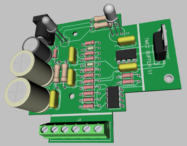
Armed with the mechanical knowledge gained by assembling the first prototype, I did a re-spin of the board to fix all the things I saw wring with the first layout. I optimized the buffer circuit section component layout, and sized the board properly for the enclosure. I also moved the LED's so they'll be correctly positioned on the flat part of the enclosure. The holes in the middle of the board mount the board on the bottom plate of the case. Hopefully, this is the "final" layout.
We are sailing along!


