See embedded answers.
walt rapp posted:gunrunnerjohn posted:I've completed the diagram so that it will work for the SPDT relay case. Note that the insulated rail is just that, totally insulated from the outside rail. The coil and the relay arm both connect to track power to light the lights and power the relay.
John, took your advice and studied your diagram in detail and I believe I have it now, so a big thanks.
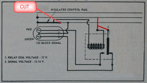
As was explained, the green light is lit, the engine hits the insulated rail and the red light goes on and the green light turns off.
In the Lionel diagram, why do they show an insulated section to the left of the track with the insulated rail????? Also, why not on both sides of it then?
The red light goes on as you go by the signal, I'm assuming the direction of travel is from right to left in this sample.
The insulated rail is only on ONE side of the track, if both were insulated, the locomotive would have no power! The idea of the insulated track is to make a contact from the insulated section to the other outside track thus completing the connection and powering the relay coil to close the relay.
QUESTION: what triggers the green light to come back on or is it simply that when the red "connection" is de-energized by default the green 'connection' gets re-energized?
The relay has a normally open and normally closed contact, when at rest (not energized), the normally closed contact is closed, that powers the green lamp.
I think my list of questions is done with this post - I hope! Assuming these 2 are answered that is.
Again, as always, thanks - walt