First off, great work, John. I'm glad you are getting things to work and you're not having much trouble with the components or Arduino coding.
I'm still plugging away at this project as time allows, hoping to make a solution that is useable by anyone that wants to throw the parts together.
Up until now my progress has been pretty much in parallel with the prototype JohnF has posted above. I use some slightly different components but the functionality is about the same. As of now, however I'm changing directions as a "less-complex" idea has come to me. Before getting into that, I figured I'd share some of the layout and such I had completed.
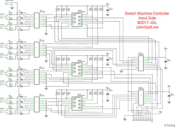
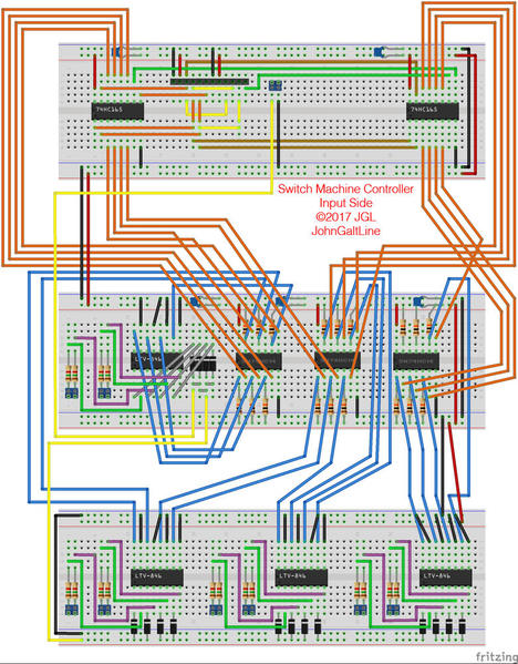
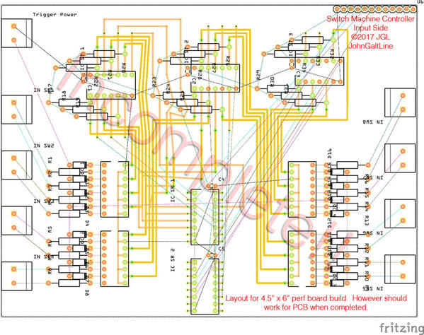
This was the input side of the project, this board capable of sensing inputs for 8 switches. It also allows for daisy-chaining of several more identical boards to control more switches. The PCB layout is unfinished as I came up with a new idea to try out while working on it. It's also not a real PCB design, but instead intended to be built on perforated proto-board in a common 4.5" x 6" size.
While working on this project some of my main goals were to keep cost as low as possible, and to make it build-able by folks with little experience in electronics. I used through-hole components for ease of assembly, and used inexpensive, common, components wherever possible. All told this input module isn't the worst thing ever, but I think I can do better. The cost is somewhere right around $12 in parts for this half of the circuit, which isn't all that bad, but it is way more complex for that cost than I'd like.
On to the controller version 2.0:
I'm going to try out replacing the Schmitt triggers and Parallel to Serial shift registers with a micro-controller. For about the same part cost (in the sort of low quantities we're using here) an Arduino Pro mini can replace 7 IC's on the board. All of the information I've found so far seems to suggest it's going to work the way I'm thinking it, but I'll need to throughly test before I know. I may also look to see if it's practical to use just the ATmega chip instead of a whole arduino board. If that works out I think I can get the parts cost down quite a bit while also making the entire project less complex for someone to build.
One other factor I'm working on, though not a top priority, is trying to make the final board as small as possible, while retaining the easy to assemble factor. If I can get the board small enough, it may be practical to use a PCB fab house to make a run of boards, greatly reducing the amount of wiring needed. At this point the 4.5x6" design would cost about $25 for a PCB, and considering that is only half of the electronics needed for 8 switches, it seems an impractical cost. If I can get the whole apparatus to fit on a $10 PCB, however, that may be feasible. Using surface mount parts would help a lot here, but honestly I don't think that contributes to making things easy to assemble.
Anyway, I'll keep you up to date with what I figure out over the next couple days.
Ill finish up with a couple design questions for those playing along at home:
Is it acceptable for all boards/ parts of this system to be located in one place, with input/output wires running across the entire layout, or is it beneficial to allow modules to be placed about the layout at a slightly higher cost per module?
Also, is it beneficial to have separate inputs for buttons and the anti-derail tracks? my thinking is that you would want the switch to ignore remote throws if a train is on the switch going the other way.
JGL


