Your link to Voltage Dividers is to instructions on how to save a webpage:
...how-to-save-all-the-webpages-linked-from-one...
Whatever.
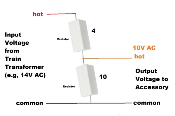
You are correct that a 2-resistor divider is a technique to create a reduced voltage with excellent precision based on the ratio of the resistor values.
So for example, starting from a 14V AC Accessory voltage, a 2-resistor divider with resistor ratio of 10:4 as shown above would divide/reduce the 14V to 10V AC at the junction of the 2 resistors.
If measured with a voltmeter (which is a negligible load) the meter would read 10 Volts. And the contrived "goal" of reducing the voltage by 4 Volts would be met.
BUT. As soon as the accessory draws any current to operate as an accessory, the output voltage would drop below 10 Volts. It becomes a "do the math" scenario depending on how much current the 2 resistors draw relative to how much additional current the accessory draws. In round numbers, what they teach you in electrical engineering class is to set the divider's current draw to, say, 10 times the current draw of the accessory. Again, you have to do the math but what this does is make the effect of the load 10 times smaller than without the resistor divider (i.e., with just 1 resistor). The penalty, if you can call it that, is the divider circuit is constantly burning power...and lots of it...just to demote the effect of the incremental current when the accessory itself is triggered.
I'm not satisfied with my explanation but, if I understand what you mean by resistor divider, I don't think it's a practical solution to the Dispatch Board.


