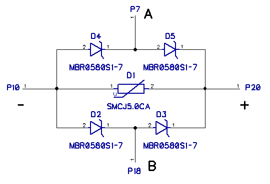
Ryaninspiron posted:gunrunnerjohn posted:You obviously didn't see my much simpler board to address the issue. The Gerber files and schematic are attached. I do these in .031 thick boards. You simply glue this to the top of the ACT244 with the large TVS down and run the four wires from the indicated connections to the matching pin of the ACT244. The large TVS diodes is across the power/ground, and the four Schottky diodes couple the voltage limiting to the pins while limiting the stray capacitance from the TVS.
Obviously, you orient this board so that the connections on this board line up with the IC pins!
So would you say that this TVS diode (due to its size) solution can be expected to last as long as Adrian's 1n4148 solution?
I am torn a bit on which solution to suggest for my club considering they have 5 TIUs all channels in use, and I can get 100 1n4148 delivered from amazon in one day for $5. I also have perfboard on hand. I cannot do the same with The SMD components. I have no issue soldering with a hotair rework station either. I am of course more concerned about what would be a one and done solution. My club (TMB) has serious output issues based on my old 1980s analog scope(100 MHz Textronix)+120Hz lowpass filter based analysis. They loose control of things like the horn on various positions of the layout. I am willing to gamble it might be those little 9v tvs diodes.
Both solutions (Adrian's "beefy clamp" board and your smaller board) are attached to the 74ACT244 right? (or can the "beefy clamp" only be hooked up to the underside of the signal transformers at the points shown in "Service Bulletin 5-22-18A" ?) (or it that just two ends of the same trace?)
Either of these solutions supplant the MTH accepted (Service Bulletin 5-22-18A) fix right?
In general is it a sign of bad TVS diodes if each TIU (PASSIVE MODE) output channel is drawing 0.2Amps? One of main rail lines(several hundred feet long) has a 2 Amp draw with an empty track as soon as the TIUs are connected.
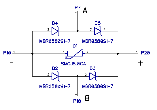
Mine just sits on top of the ACT244, it's fairly easy to install, but it does require some "fine" soldering to the ACT244 leads. I use #30 wirewrap wire to make the connections. I did a "final" tweak to the layout, but I haven't built any of these yet. Electrically, they're the same as the previous version, I just put some holes for the wires as it makes it a lot easier to keep them from coming loose as you solder the other end to the chip lead. Even with #30 wire, enough heat came up the wire to unsolder it, it was a bit of a pita. With the holes, you can tun the wire through and lay it over, even if it momentarily melts the solder, the wire won't just fall out.
I've only put this on a couple of TIU's, and I don't get the abuse that Adrian's club dishes out, but there have been no failures and no channel degradation. Obviously, it would be nice if it had a wider exposure before declaring it a "tested" fix, but I believe it is doing the job.
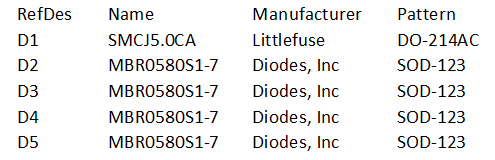
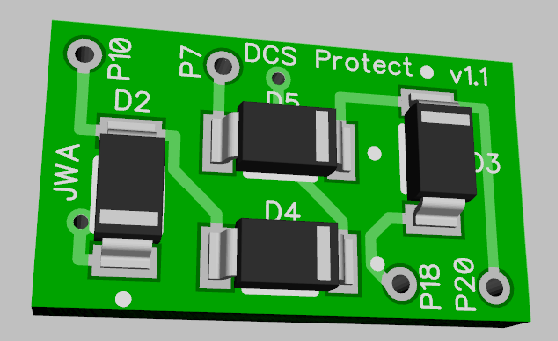
Below is the BOM, schematic, and Gerber files if you want to use this. The boards are so small that it's fairly cost effective to get them at OSHPark, and I get them in the .031 material with 2oz copper.