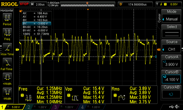
Adrian! posted:rad400 posted:Adrian! posted:rad400 posted:Ringy? Please explain? These are suppose to be square waves, but in all of the pictures that we have all shown, none of them are square. Is the so call "square wave" suppose to look as we have shown them in the photos or is there a lot of distortion being introduced some where in the circuit?
Bob D
It's a square wave plus an e^(yt) x cos(wt) term from all the wire inductance like the last part of the tutorial talks about. The amplitude is fine and if johnf tightened up the loops in the wire it's be a square.
The part I am not following is the measurements that I have taken, have been straight off the output terminals of the TIU (no track wiring), where the impedance should be very low (small R) resulting in minimal ringing. But I still seem to be getting a lot of ringing? What am I missing?
Sorry for all the questions. Thanks
I think the discrepancy is some of us are using high speed scope probes (low L) and some of us aren’t. The TIU itself has a transformer at the output so it may ring if it’s not de-Q-Ed by the scope probe. I think this plot and the other one by Johnf are fine. Those overshoots won’t do much to the decoder since the one and zero levels are very clear
Adrain thanks. I am trying to address the DCS issues at the club and wanted to make sure that I am dealing with TIUs which are generating a good signal before address layout issues.


