


Stewart - Just starting to wire my layout and am practicing on a couple of 072 atlas switches joined to form a simple (and short) siding. I have the 6924 non-derail board and a dwarf signal kit 6931 which comes with a circuit board. After looking at the Atlas wiring instructions for this combination, it appears I do not need the board supplied with the 6931 kit because I should be able to control the dwarf signal directly from the 6924 - J3. Can you confirm this? That is correct, be sure to enable jumper JP1. Com1/C1(1)/C2(1)Terminals can not be used for anything else.
I used the small boards provided with the 6931 dwarf lights for two reasons.
(1.) My 6924 boards are centrally located. It was easier to hook the 6931 dwarf lights directly to the switch motor as the diagram shows.
(2.) By not using the Com1/C1(1)/C1(2) relay for the dwarf lights, it was still available for power routing. Some of my switch cross over combinations required the used of both relays on the board, there were two track circuits involve in the cross over.
A few more questions - The instruction say the 6924 will work for 2 switches, but I don't think I see how to wire a second switch (Paired cross over switches (2)), is where this function is normally uses. Both switches have to be either diverged or straight at the same time. The Outputs from the 6924 board can power both switches at the same time either Through or Out. It is interesting to note that You will probably not have to hookup the diverge non-derail input for a very short cross over. and last, if I am reading the diagram right, I must connect 2 wires to the isolated rails right near the switch convergence, which seems like last second switching when the derail detection occurs. Is there a way to move detection out further with an isolated rail prior to actually getting on the switch track? Yes, You can cut an isolated rail section further back on the track.
Between the two switch motors to the right are two isolated sections for the (3way) switch pictured. Note the small white piece of styrene used when the Gargrave track was cut to provide the isolated section. The isolated sections are non-derail inputs for the left "Y" and the right "Y" of this three way switch. Note that the two isolated sections are staggered, you need outside rail common via the train axle to activated the non-derail. Two isolated sections across from each other would not work.
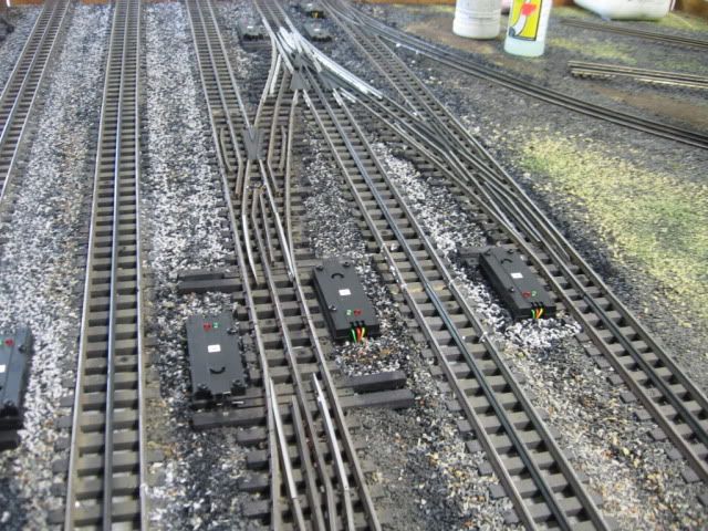
Usually this input location works well for quick-acting snap switches. Slow moving tortoise switches may require either slow moving trains through the switch or as you suggested moving the non-derail input back away from the switch frog.
Thanks,
Mike Monjure
Thank You! I do think I get the staggering, if you do not stagger the cuts, it would effectively open the circuit. I assume that your inputs to the 6924 are connected between the 3 way switch and the isolation cuts, correct? And just to be sure, their is no cut at all on the center rail?
