


Well Done![]() , a few comments, via observation of your work/photo.
, a few comments, via observation of your work/photo.
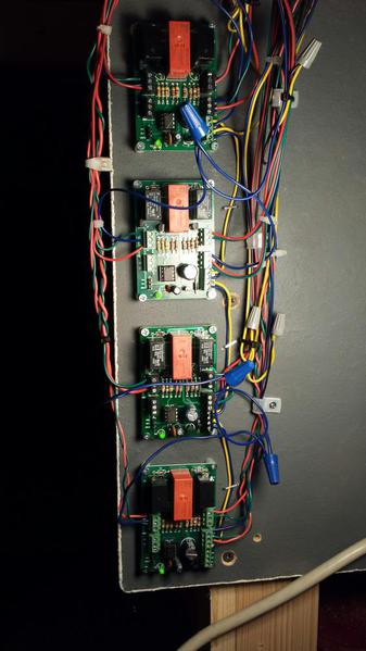
Left side of board(s).
(1.) Blue (J1) wire is SW PWR IN. J1 terminals
(2) Green (IN A) (J1) and Red (IN B) (J1) would be Through and Out push buttons, also used for automatic non-derail input feature.
(3.) Not shown, I assume that all blue input wiring is fused.
(4.) (3) relay terminals not used (J2) middle left side are a second relay that can do two things:
One, as wired, it logically powers the three small plug-in terminals bottom left that can be used for dwarf lights.
Two, remove jumper JP, it can be use as an additional power routing relay.
Right side of board(s)
(4.) Green (OUT A) (J4) and Red (OUT B) (J4) wires top terminal, would be wired to the through and out terminals on the switch motor.
(5) Blue in, from the right, would be Track Power to an available relay that will Power Route, dead rail track sections of the switch. It appears that both switch motor power and dead rail track section power are the same power source.
(6) Red and Green are wires that attach to the dead rail sections, center of switch. As wired, this is also fused power, to prevent board damage.
(7) Yellow and Blue are daisy chained wires that power the 6924 relay boards.
Comment:
As wired, if your fuse blows, you will loose all switch motor(s) function, If you fuse each 6924 board/switch motor separately, you will only loose that switch motor if the fuse blows. Fuse/over current protection is not shown in these pictures.
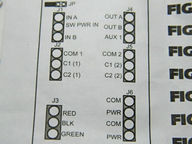
Atlas Power Routing/6924 relay board wiring from the Atlas website.
![]() Best wishes
Best wishes ![]()
Mike CT
