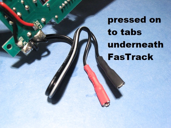
@stan2004 posted:On all the pics, diagrams, drawings I've seen there is a DPDT selector switch which chooses between 2-wire Track Power or 2-wire Accessory Power. In the photo above you can see that the black wires are on the "upper" row (one DPDT pole) and the red wires are on the "lower" row (the other DPDT pole).
So when you ask how the track power "polarity" correlates to the Aux/Acc power "polarity" I guess it depends if the user presses the red heat-shrinked tab to the center-rail and the black heat-shrinked tab to the outer-rail. Obviously these could be pushed on to the FasTrack tabs backwards to reverse polarity.
Only to the Auxiliary Power Supply terminals, Not the ACC terminals. I hope that was a mislabeling in yellow above?
I cannot tell which wire is attached to the solder tab marked RED, I assume it is the one for the RED push-on connector. And unless there is some obscure note in the box about selecting different attachment positions for different outputs, then normal connector assignment would be BLK to outer rail, which is track common, the same as layout common ground. Given that, it looks like BLK/common ground in this case is going to the Left terminal of the Auxiliary Power Supply. Am I seeing that correctly Stan?
What I am trying to establish here is the actual common ground terminal of the Auxiliary Power Supply connector, regardless of the nomenclature used by the mfg. That is what caused problems for the application diagrams.
Dave


