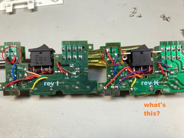
@Dtrainmaster posted:Stan, your first pic is what I was thinking also, although I don't care for the way that unit switches the ACC GND. Does that have a bridge or single diode?
But I disagree with the alteration in your second pic.
Assuming nothing else is tied to the trace, unsolder the RED wire and extend it to the diode's right solder pad. Cut the trace only between Relay Common and the diode. You don't want to break that trace between ACC PWR and Relay Common, nor the one between ACC GND and the BLK wire.
I hear you. OTOH, look at the rev K photo that Rod took. Notice the circled pad labeled "what's this?". Compared to the rev I version it looks like there's a component terminal coming thru to a round solder pad? I think Rod has already contributed above and beyond so we shouldn't impose on him to see if there's something there.
Separately. To your point about the diode vs. bridge rectifier. It appears these earlier version used just a diode (half-wave) instead of a bridge for providing DC for the electronics. There is a 7805 TO-220 5V regulator chip right after the diode.
In any case, I thought there "might" be some advantage to making the modified 153IR units (isolated relay common) have a consistent terminal configuration with the isolated relay common in the same position of the 4-terminal block. Potato potahto. As I've stated before, and as apparently others too have observed, when you get to the point of cutting PCB traces and soldering jumpers and wondering what to do if you have revision A vs. B vs. H, J, K or who knows what...then it's Visine time to combat the eyes glazing over. ![]()


