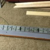
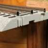
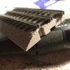
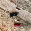
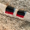
Yes - that's what I meant by "cuts". One of the unanticipated issues with pulling the pins where two pieces of FT will meet for a liftout (rather than just cutting the track) is that even after pulling the pins, there are still plastic nubs and connectors that snap together to hold the FT together and they have to be removed to allow the track to simply lift straight up w/o having to disengage one piece of track from the other. There is also a small "tab" and "slot" on each side of the roadbed that also helps join two pieces of FT together. You have to cut off the one on the track piece that is on the layout, but you can leave the one on the liftout section to help align the track. It was short work with a Dremel and grinding stone and the three places where the track meets align very well, both horizontally and vertically.
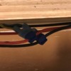
The liftout side of the extension is completed except for some edging/veneer on the edges. I ran 3 parallel 14ga. wires from the main distribution panel to the edge of the liftout. I had first soldered the Anderson Power Pole connectors to the ends of each wire and ran the other ends over to the panel and crimped spade connectors on and screwed them to the panel and tested for power. I then made 3 pairs of wires the width of the liftout with power poles soldered on each end and clamped that to the underside of the liftout. All of the Power Pole connectors were ganged together (3 black, 3 red) on all the wire ends. I had already soldered a power drop to the underside of the FT on the liftout and drilled through the liftout and ran the wires down. I took one of the three pairs of wires attached to the liftout and slightly separated the red and black wires and attached a T-tap connector to them and then to the power drop leads to the track on the liftout. I turned power on and the switch lantern on the liftout lit up so I knew I had good power to the liftout.
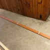
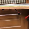
I was able to pop off the knotty pine shelf cap (pic attached) on the closet side of the door which provided a way to drill a hole through to run and hide the long wires to the other side of the closets. I had stained and mounted wire clamps to the bottom of the long oak board running through the closets and glued the 1/4" foam road bed made for FT on the top side of the board. I also hardwired on the underneath side all the FT that was going through the closets and placed that on top of the roadbed and put the board in place through the closets. I then cut 3 long pairs of wires (up to 30' long) and soldered the power pole connectors on one end to connect to the liftout wires and ran the other ends through the hole in the shelf cap ; through the wire clamps on the underside of the oak board; and out the other end. I drilled a small hole at my work bench for the wires to exit.
One of the 3 wires will end at my workbench and supply power to the track along the window. The other two will supply power to each side of the reversing loop. In the closet I had also previously soldered a set of power drops to the underside of the FT on the oak board and drilled through and ran the wires out the bottom before putting the board through the closets. I installed another T-tap connection in the closet to power the track on the board and then connected all 3 wires to the liftout connectors. I measured tack voltage and the ends of the 3 wires on the other side of the closets and have very little, if any, power loss. I ran a train through and back with no issues, so I would say the liftout side is done.
I'll pick up a sheet of plywood and some framing lumber this week to start the reversing loop section.
Couple of Notes - the Anderson Power Pole connectors (30A) are not the easiest connectors to work with and probably overkill for this application, but I've used them since my old R/C racing days and they are bulletproof. I also used the T-tap connectors for the first time and really like them. They are basically a "suitcase" type connector that allows the main wire to simply pass through, but with a hole/tap on the side for a second wire to attach t the main wire via a crimp connection.


