I didnt return until later evening so I had limited time to experiment and test but I scoped the zw as promised and if this works, following are 3 freeze displays:
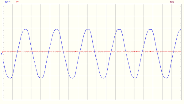
First, the ZW at minimal track voltage. open load where my RMS DMM told me I had 8.67v, we expect, and do see this:
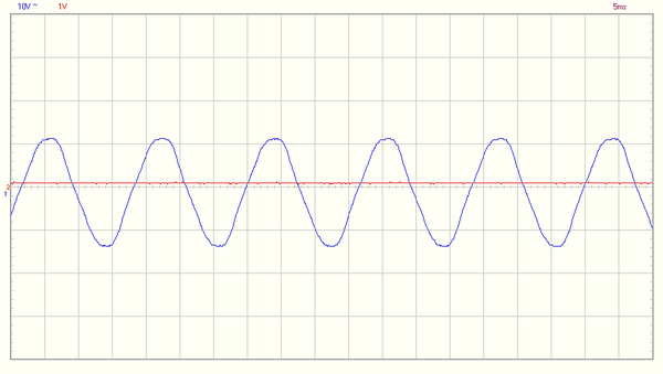 Note that at 5ms display we see a wave period of 16.7ms. This was before I put the scope in RMS mode, it said my rms voltage was 8.9v - close enuf
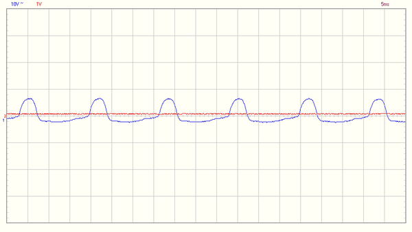
Next I slowly pushed the whistle lever forward until it broke the tie on the upper part of the switch, but had not yet made the diode plus shunt. we expect to see the effect of a half wave rectifier on a 5.something v ac winding:
The voltage max appears to adhere to the theoretical .45VRMS and the shallow floor I would expect from a coupled probe draining. I am told the tender relay has 2 copper discs (mini rectifiers?) to keep it from building and emf via its impedance. recall, on AC a coil has impedance (R+Z) and the transformer has effectively a damping factor of 0 so you want to minimize this as much as possible.
This wave would serve to cause the coil to energize in 1 direction 60 times a second, due to DC inspired emf collapse, the holding current never goes to 0
Lastly, I completed the lever push, now AC and DC are supplied via the diode and the shunt
I had used my dmm (btw the dc supplied by the diode was fluctuating between 5.9-6.3v - unfiltered as it was - and got 14.28vrms. the scope is showing appx 20v when you remove the noise offset, 14.14v - close enuf as the interfering DC is going to add a clamping effect (keeps the relay on) and the higher voltage (this is still open circuit) is supposed to run the motors in the loco AND the tender now. everyone seems to say it works. some even say things speed up a bit. oh and the scope could not figure out vrms...with the DC signal helping one side and hurting the other, I guess the comparator was flumoxed.
why do I constantly have a wee bit of offset? the scope I am using - velleman pclab 2000se - runs off pure USB DC into this laptop. the transformer has no ground connection and as I said before, is noisy as ****...it floats a wee bit and while the PO put on a polarized plug, I bet if I reversed the wires in the plug, it would float on the upper end now. there is no need to put a polarized plug on a zw, primary shares no connection with any secondary and there is no center tap nor equipment ground.
summary: this is what we expect to see in properly functioning zw as built by lionel. I am using the 100ohm 10w cement to limit DC current. But I have not actually tested a whistle on it. The mth stuff works fine, but I dont think I have any old school lionel in stock. I got a couple erie builts with a b unit, will go check if that has something onboard, and I have a korean war berk I gotta grab from the store and check.
my goal is to find the largest resistor that allows the whistle to blow, then I can select the smallest diode to effect this and finally come up with a comprehensive BOM to rebuild a ZW, both sides, including lighting so stay tuned.
PS: picked up 4 in the box 1044s from an estate sale last night, they will added to the fold.


