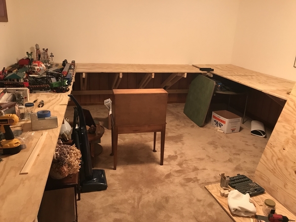
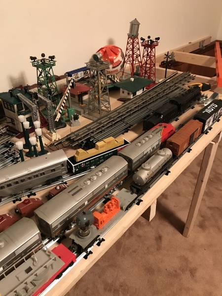
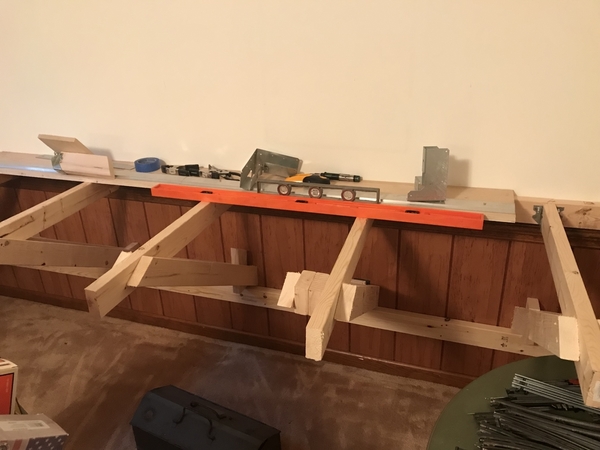
5C754D57-6751-452B-AF14-C1FDBA4E36CB67D862AD-9976-45FA-9985-2F6D9E56CCC42D3F43AA-CF8E-4767-B512-5D85864978DFThought I would show the progress on this layout build. It’s a cantilever design, no legs on the floor. Started out as a circle around the Christmas tree 1964, will have to post that photo.  

There are a few modern items mixed in, this is a close copy of what Dad and I built in the 70’s, only on a larger scale. And after all these years, I finally figured out that page in the crusty manual titled “multiple train operation”!!! 

Attachments

Images (3)
  • 5C754D57-6751-452B-AF14-C1FDBA4E36CB
  • 67D862AD-9976-45FA-9985-2F6D9E56CCC4
  • 2D3F43AA-CF8E-4767-B512-5D85864978DF
Original Post

Replies sorted oldest to newest

DC0E65B6-9906-4DAB-98CE-804C6411E5EBStandard sheets of plywood were used. On the left are two 4’x8’s, center is one 4’x8’, right is one 4’x8’ plus a partial that is somewhat hidden. There is a closet behind the sheet of plywood on the right. I cut the plywood down to 38” wide, a length I can comfortably reach across for access. The room is roughly 14’ wide by 24’ in length. I could go longer, wanted to leave room for the steps where I was standing, access to the half bath and door leading out to the garage. We do have to keep a level head. As noted above

There will be a 90 degree crossover by the closet and left side for future expansion, a “hinged” bridge on either side, so there is no crawling underneath, if that makes sense. For now it will remain open in the center.

I agree on the holes for pulling the wires, easily done and a few strategically placed buss bars from MTH will help keep things clean.

Opposite the wall on the right is my unfinished utility room/ canned goods/potato’s storage, so I might, and this is a big might, have a small exit in the far corner only to re-enter by the closet. It would be interesting having track running between Mason jars of garden tomato’s, brandied peaches and other specialties. It would have to be sealed off when not in use.

Attachments

Images (1)
  • DC0E65B6-9906-4DAB-98CE-804C6411E5EB

Sounds like it is well planned. 

Have you considered pulling a hot and common of 12 awg all the way around for a bus and using tap splices? 

Same concept for accessory power of AC and /or DC perhaps in 14 or 16 awg. Accessory controllers can be localized off of a bus power scheme.

100' rolls will do ya...

Pull the wires now before you screw down the deck.

I will post updated photos soon, right now I have a question regarding 022 switches.

Here is a link I stumbled across, extending the 022 switch activation range copied and pasted below. http://www.toytrainrevue.com


If your switches don't seem to activate by an on-coming train fast enough, you can use an insulated track section to extend the non-derailing feature of the switch. An insulated track section also works to create non-derailing switches out of versions like the 1121 for O-27 which don't normally incorporate this feature.

Anyone ever do this? I think it would add a bit of realism if the switch activated (if necessary) further ahead rather than when the engine just started to enter the switch. I assume the fibre pins would still stay in their usual places in the switch and let’s say three sections of insulated rail would suffice (outer rail insulated and fibre pin). 
Make sense? 

Thanks in advance. Alan 

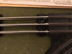
28FA71DF-6DAE-4348-B77C-7190B4B91D88E20ACB2C-2432-46E6-8886-5FA1000A3C2AE4ABF106-E8EF-49FB-90A6-26D7239D39CCWell after some experiments I have this to report. 
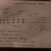
The mainline side of the O22 switch uses all steel pins. Two sections of 10” insulated rail join to this side of the switch. The lower and center rail are insulated. The fibre pin that would normally be at the switch is relocated to the lower rail as seen in the center image. The drawing should explain this. 
When the train enters track 2 (see drawing) if the switch is not set for mainline passing, it sets itself correctly. 
I can see making a custom insulated piece of track out of a longer section so the switch would throw 30” from the switch rather than 10” from the switch. Add a block signal for more realistic operation. 
Why it takes two sections of insulated track is beyond me, the answer might be staring right at me.

Hope this helps someone else.

Attachments

Images (3)
  • E4ABF106-E8EF-49FB-90A6-26D7239D39CC: Mainline at switch
  • E20ACB2C-2432-46E6-8886-5FA1000A3C2A: Insulated track sections
  • 28FA71DF-6DAE-4348-B77C-7190B4B91D88: Drawing

Yes, you can extend the trigger rail or add another elsewhere by using isolated rails and fiber pins/gaps.

Long trains and long rails will cause the antiderail to remain active a lot. They may heat up and overheat,depending on voltage.  These coils need some "off time" to recover from heat build-up. (electromagnets get HOT).

The only reason for a center rail fiber pin I can think of might be block control. (I have a block that ends on a turnout.)

  Also, a note along the anti-derail theme; some turnouts will kill power to the center rail of the EXIT that is not aligned. And so reverse travel thru either of a turnouts exits may be stopped (more common on manual turnouts).  In this case the center rail of the track connected to an exit gets the pin, making the "dead rail extension" ling enough to work. I could see a novice moving that closer to a turnout.  (it's a turnout in real life. It has an entrance, and thru exit, and deviation exit. Reverse travel is not necessarily a loco moving in reverse but is moving thru the turnout from an exit towards the entrance)

Which engine are you running? It could be the weight of the wheels/axle set is not enough to make contact between the two outside rails and trigger the non-derail.

Extending the trigger section is a common practice to meet the operational needs of the layout. 

Attached is the 1954 Lionel Operator's Booklet in case you don't have something like it. Page 25 has the O22 switches. 

What does the table & track plan progress look like?  I really liked that you cantilevered the table supports. Good appearance.

Attachments

Files (1)

Wow, a lot of helpful information. It always amazes me the various information that is available from manuals spanning a variety of years. My manual is yellow, I think it’s 1954.

Pages 33 and 34 have interesting layouts and page 38 shows the insulated section similar to what I am doing. I’m not sure of the reason to have an insulated track section on the entrance side illustrated on page 38. 

All the O22 switches I have now work correctly, when the engine contacts the rails, if the curved rail is set incorrectly it snaps back to the mainline. Having it activate further back (only if necessary) about three feet from the switch, and combined with a block signal, in my opinion will add to realism, let’s say the block signal shows red, the mainline is not clear, the switch is not in the correct position. As the train enters the insulated block, it switches open the signal shows green and the train continues on. 
I’ll only do this once in a while, to avoid overheating. 
Sometime soon I’ll post some photos, right now the track is loose, trying out different layout options. 

AlanOGauge posted:

Wow, a lot of helpful information. It always amazes me the various information that is available from manuals spanning a variety of years. My manual is yellow, I think it’s 1954.

Pages 33 and 34 have interesting layouts and page 38 shows the insulated section similar to what I am doing.I’m not sure of the reason to have an insulated track section on the entrance side illustrated on page 38. 

The left side middle to bottom describes that a switch tower - guy that goes up and down stairs ( I see that you have one with the green roof) - would use that U rail to trigger the action. (top right illustration) The tower would have the HOT from the transformer

All the O22 switches I have now work correctly, when the engine contacts the rails, if the curved rail is set incorrectly it snaps back to the mainline. Having it activate further back (only if necessary) about three feet from the switch, and combined with a block signal, in my opinion will add to realism, let’s say the block signal shows red, the mainline is not clear, the switch is not in the correct position. As the train enters the insulated block, it switches open the signal shows green and the train continues on. 
I’ll only do this once in a while, to avoid overheating. 
Sometime soon I’ll post some photos, right now the track is loose, trying out different layout options. 


Last edited by Moonman
Moonman posted:
AlanOGauge posted:

Wow, a lot of helpful information. It always amazes me the various information that is available from manuals spanning a variety of years. My manual is yellow, I think it’s 1954.

Pages 33 and 34 have interesting layouts and page 38 shows the insulated section similar to what I am doing.I’m not sure of the reason to have an insulated track section on the entrance side illustrated on page 38. 

The left side middle to bottom describes that a switch tower - guy that goes up and down stairs ( I see that you have one with the green roof) - would use that U rail to trigger the action. (top right illustration) It is taking the U (common) from the switch terminal to the lockon) The tower would have the HOT from the transformer

All the O22 switches I have now work correctly, when the engine contacts the rails, if the curved rail is set incorrectly it snaps back to the mainline. Having it activate further back (only if necessary) about three feet from the switch, and combined with a block signal, in my opinion will add to realism, let’s say the block signal shows red, the mainline is not clear, the switch is not in the correct position. As the train enters the insulated block, it switches open the signal shows green and the train continues on. 
I’ll only do this once in a while, to avoid overheating. 
Sometime soon I’ll post some photos, right now the track is loose, trying out different layout options. 


Last edited by Moonman

Here is a short video of my test. The switch is set as to let a train out of a siding, or have an oncoming train trip it back to opening the mainline once it starts to make contact with the switch under normal conditions. 
What I did is this. As illustrated in the original attached sketch two insulated rails are used, only this time I made one out of a piece of 30” tubular track from Menards (less ties to fiddle with). It joins with the switch and the 10” insulated rail joins with it. The remaining track in the layout remains normal. 
When the train enters the longer insulated track, the switch reverts to “mainline open” if that is the correct terminology. 
I have no intention of doing this every time the train comes around to this point, it’s just to add a bit of fun. Might try with the 450 signal bridge or a MTH cantilevered signal bridge. 

Attachments

Videos (1)
trim.EB682F85-6443-4E33-9354-9BC83F21275F

I like the extended trigger track for the non-derail - it provides a comfort level that the switch will get to the THRU position (mainline open) when running the train. 

I liked to run the mainline train at high speed occasionally. I was always wary, even with FasTrack switches, waiting until inches from the switch that it would auto switch to the THRU position when I forgot to realign it. 

There are more than a few good extended threads about setting up "block" signaling, also. Green, yellow and red or just green and red using IR triggers.

You are correct that adding signal lights does add to the play value.

It's been quite a while, finally got back to laying down track, trying out different ideas etc. After struggling with relays, trying to understand what wire goes where and having a few go up in smoke, went back to the old school way with fibre pins, lockons interconnected, a few pieces of insulated track, with a minor modification to fibre pin placement in one of the blocks, (stops one train further back allowing the second train to clear an O22 switch)it works as expected.

Will post an image of the track plan, from one of the old Lionel manuals with my notes.

Here are the two images, the first Track Plan 1 with reversing loops is what I have laid out, the reversing loop on the bottom is on the right side of the layout. I moved block "A" back a few track sections, this gives extra wiggle room for trains to clear each other.

The second is from my manual dated 1952, at one time before I started the current layout, I used the plan on the left on two sheets of 4x8 plywood, joined end to end to make a 16 foot length of track.

I'll have a 153ir around or before block "A" that will trigger a signal from green to red in block "A", but have a short duration, giving enough time for the train to clear Block C1, allowing the train in block "A" to leave, not jumping as the light changes to green, allowing for a few seconds of delay, if that makes sense.

Not sure if Lionel ever put out a book/manual off all these old track plans that use this simple technology. The beauty of this is these simple plans can be modified without difficulty, ie: the plan from Track Plan 1 on the right is the same as the plan on the right from Track Plan 2, the reversing loops have been moved outward rather than inward.
Attachments

Images (2)
  • Track Plan 1
  • Track Plan 2
Last edited by AlanOGauge

Add Reply

Post
The Track Planning and Layout Design Forum is sponsored by

AN OGR FORUM CHARTER SPONSOR

OGR Publishing, Inc., 1310 Eastside Centre Ct, Suite 6, Mountain Home, AR 72653
800-980-OGRR (6477)
www.ogaugerr.com

×
×
×
×
Link copied to your clipboard.
×
×