John,
You have a couple of choices here. The remote control track (6019 and the UCS) normally get their voltage directly from the track. Much of the time, one would simply stop the train engine so the operating car is on the the remote control track, make sure the engine in the "neutral" position, and then adjust the AC voltage to the track to control the voltage to the remote control track.
The other option, which I do, is to wire the UCS directly to a dedicated transformer. I then adjust the voltage as needed to operate the car / accessory. One bit of caution, you have to be sure the power to the track and to the UCS are in phase (in sync). You will have no issues if you are using the same transformer to power the track as you are using to power the accessories. For example, using a ZW, and use the "B" or "C" power post to the UCS. The large ZW handles power the posts "A" and "D" which is for normal track control. However, if you are using a separate transformer, make sure the common is "common" between the transformers. You can check this by using a volt meter between the two.
Let me know if you need more info.
Best, Dave
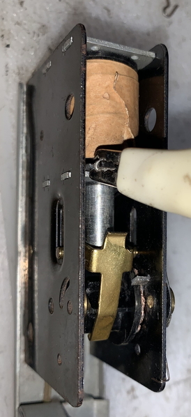
![]() Haven't tore into one before and it appears there is little on the web. The mechanism to eject the boxes is working, but the door won't open automatically. The 6 position ratchet doesn't increment. I manually incremented it and I'm guessing the lever that drives the door open and closed is broken. I assume there is a pin from the lever that opens the door with the ratchet. Does anyone have any pictures or drawings of this mechanism?
Haven't tore into one before and it appears there is little on the web. The mechanism to eject the boxes is working, but the door won't open automatically. The 6 position ratchet doesn't increment. I manually incremented it and I'm guessing the lever that drives the door open and closed is broken. I assume there is a pin from the lever that opens the door with the ratchet. Does anyone have any pictures or drawings of this mechanism?


