hello guys... i am trying to make a postwar 153 signal work. I went to radio shack and picked up a DPDT ac relay and cant figure out how to make the signal work. Any help would be appreciated.
Original Post


|
|
hello guys... i am trying to make a postwar 153 signal work. I went to radio shack and picked up a DPDT ac relay and cant figure out how to make the signal work. Any help would be appreciated.
Replies sorted oldest to newest
What is the coil voltage rating on the relay?
What transformer are you using?
Have you created an insulated outside rail section (or sections)?
Do you know which two terminals on the relay are connected to the coil?
To learn by doing, I suggest that you get yourself a cheapo analog or digital voltmeter (about 12 bucks) and some test leads with alligator clips. Using these, you can do each step temporarily until you begin to see the circuit being developed. This method also ensures that you don't burn out anything if your wiring is incorrect. Then do the final wiring in a neat and orderly way. Digital meters are good for checking or comparing steady readings, while analog ones are good for watching the operation of a circuit. The movement of the needle is easier to see than the changing display on a digital one. I use one of each for these reasons.
Start by creating the insulated rail section. Connect one terminal of the coil (it doesn't matter which) to the insulated rail. Connect the other coil terminal to a constant voltage source on the transformer that shares a common return with your track power. (This is the transformer terminal that already goes to the outside rail of the track.)
Take a rail car and place it on the track at a point away from the insulated rail. With the transformer on, roll the car onto the insulated rail. The relay coil should operate. (You will hear it and if the relay cover is transparent, you will see the relay armature move.)
Now it's time to wire the contacts of the relay to the signal terminals. You only need one set of the relay contacts, what we call the "transfer" or "form C" contacts. The normally-closed contact, often labeled as "NC" gets connected to the green signal lamp terminal. The normally-open relay contact, often labeled "NO" gets connected to the red signal terminal. The common contact, often labeled "C" or "COM" gets connected to the transformer post that provides 12 - 14 volts AC ("hot" side). The middle terminal of the signal gets connected to the return of the 12 -14- volt AC source ("return" side).
The relay source and the track source must share a common return. The juice for the signal lamps themselves can either share a common return or not. It can even be from another transformer.
If you can let us know how much you already know about electricity and relays, and what transformer you intend to use, we can continue.
my biggest problem is that i cant get the coil to move. I have already created an insulated section. I am doing a temporary few sections of track so i can later replicate it. I am using a cw80
A good tutorial post/thread HERE.
NYC5344 posted:I am using a cw80
This won't work with a large number of CW-80s... it depends on the date code on the bottom. Can you post a picture of the bottom of your transformer?
Can you answer my first question, please?
Please post a picture of the Signal in questions.
This is the signal that he is using.
What is there about a CW-80 that would prevent him from achieving success?
the radio shack part number is 275-0044
OK, I have Googled that part number and determined that the coil is rated at 125 Vac. The coil is the stationary part and the armature is the moving part. The armature will move if you apply 125 Vac to the coil terminals. It is not the correct relay for a low-voltage application. You need to buy a relay that has a 12 Vac coil.
Or, as has been pointed out in this thread and in countless others, the best electricity for signalling is DC. DC allows much greater versatility and control, no chattering, no drop-outs, slow release, and interesting control circuits using diode logic. DC relays in voltages from 6 to 24 are easy to find. Check out the relays available from Altronix, for example. They provide an easy screw-terminal connection method.
do you have an part numbers for a dc relay and a rectifier from radio shack? Im dont know too much about electronics and want the easiest solution I can make. Thank you
See this post by resident electronic guru GRJ:
https://ogrforum.ogaugerr.com/t...39#46904150286605339
I'm pretty sure you can get all the components he shows at Radio Shack...including a DC-coil relay. You mention the easiest solution "I can make" so I assume you don't want to buy an off-the-shelf relay module which essentially has all these components on board; they run about $15 and are available from several train suppliers.
Let me Google "12 volt AC relay" for you.
Try this one:
www. Mouser.com
Part number 653-MKS2PIAC12
1.Ok, I see the Signal that you would like use above yes or no
2. Does does both lamps work ?
3. What would to accomplish here ?
If you like you could call me if that help you out here.
John 848-992-2157
Arthur P. Bloom posted:What is there about a CW-80 that would prevent him from achieving success?
Not "a CW-80", but certain CW-80s. The ones built before date codes with a "G" in them are essentially wired out of convention, the red posts("A" & "B") are common(Black "U" under "A" is train variable, Black "U" under "B" is programmable accessory variable) instead of the black posts. This was corrected in the later version.
here's the page (attached) from the 1954 operator's manual for controlling the block signal with a relay with the wiring diagram.
Note that it also controls a track block to the left to stop second a train approaching from the rear. You can eliminate that if the feature is not needed.

Their a lot of good information.
I hope you can figure it out.
Good luck,John
NYC5344-
I found this diagram on one of the other forums, which should clarify the wiring diagram to operate a block signal via relay (instead of the mechanical 153c switch):
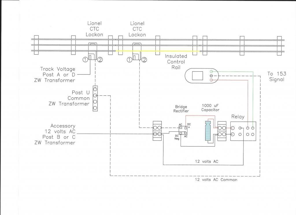
Although not show above, the red wire (for the red signal light) on the signal should be connected to the normally open (NO) contact on the relay; the green wire (for the green signal light) should be connected to the normally closed (NC) contact on the relay. In this manner the signal will remain green; the signal will change red only when a train passing through the insulated block. If you prefer to have the signal change to green only when a train is passing through the insulated block, simply reverse the NO and NC wires.
Below is a list of suggested part numbers to make the circuit:
1000uF Capacitor: Radio Shack # 2721019, 2721032 or 2721047
Full Wave Bridge Rectifier: Radio Shack #2760268, 2761173, 2761146, 2761185, or 2761181
12V Relay: Radio Shack #2750043 or 2750042
Optional parts:
Relay Plug-In Socket: Radio Shack # 2750220
Barrier Strip: Radio Shack #2740656 (2 wires), 2740658 (4 wires), 2740659 (6 wires), or 2740670 (8 wires).
Hope this helps!
-John
This is the relay and socket set I use and it will control just about all signals..

 I got all these from Galko Electronics...
Marty
Martin Derouin posted:This is the relay and socket set I use and it will control just about all signals..
I got all these from Galko Electronics...
What AC voltage are you operating at? And you're just using a bridge rectifier (no capacitor)?
It looks like you have a 12V DC-coil DPDT relay ($9.62)...
https://www.galco.com/buy/NTE-...tronics/R14-11D10-12
and 2 versions of relay socket ($2.04/$8.53):
https://www.galco.com/buy/NTE-Electronics/R95-111
https://www.galco.com/buy/NTE-Electronics/R95-110
Here are some relays with sockets for a little less. Relays have a 'push to test' feature, come assorted coil voltages, 15 amp rated contacts. Sockets are available and include bracket with label area. They also have reasonably priced aluminum din rail and free 2 day shipping on orders over $49.
General Purpose, 15A (781 / 782 / 783 / 784 Series)
I can't get the link to work properly, copy this to the search bar you get when following the link: 78x relay
I have extra Radio Shack relay if you need them from one of my 153 IR projects. If yes contact me via email which is in my profile.
AcelaNYP posted:
...12V Relay: Radio Shack #2750043 or 2750042
Optional parts:
Relay Plug-In Socket: Radio Shack # 2750220
...
I'm not commenting on suitability or recommending anything here; simply providing coil data for the suggested relays which might be useful if doing-the-math:
2750042 $5.99 12V DC coil, DPDT 5 Amp contacts. Photo shows: Sanyou SMI-S-212D. Datasheet shows coil: 200 ohms, 60 mA, 0.75 Watts. 5% dropout voltage (min), 80% pickup voltage (max), 130% max
https://www.radioshack.com/pro...y?variant=5717503685
2750043 $10.49 12V DC-coil, DPDT 10 Amp contacts. Photo shows: Sanyou SME-212DT. Datasheet shows coil: 160 ohms, 75 mA, 0.9 Watts. 10% dropout voltage (min), 75% pickup voltage (max), 110% max
https://www.radioshack.com/pro...y?variant=5717504261
2750220 $3.49 socket for 2750043
For Stan above, to answer your question, I use the R95-11 relay with a rectifier and the R95-110 socket. I went with the DC ones because I have a lot of rectifiers, I run on the accy.voltage at 13v. I don't even know what the cap is for, everything has worked well for about 10 years...
Marty
Martin Derouin posted:everything has worked well for about 10 years...
Your bottom line says it all ![]()
wow thank you guys for all of the helpful information. It really means a lot. Im going to order some relays online and I will keep you posted. Once again much appreciated.
Arthur P. Bloom posted:What is there about a CW-80 that would prevent him from achieving success?
Not a CW-80 per se but any train controller using the chopped-sine (triac) method to regulate output voltage needs special consideration when using a DC-coil relay particularly with a capacitor. Suppose we have the same AC voltage (say 12VAC, 14VAC) from a CW-80 vs. a "pure-sine" transformer's Accessory voltage terminals. After AC-to-DC conversion by single diode or by 4-diode/bridge-rectifier, the DC voltage presented to the relay coil will be higher from the CW-80. This can cause coil overheating and relay failure unless accounted for...that is, some method to drop the DC voltage to the nominal required coil voltage. Dropping the voltage is not difficult - as simple as a 2 cent resistor or as "sophisticated" as a 25 cent voltage or current regulator IC chip.
This topic seems to come up often enough that I re-post my Rogues Gallery of off-the-shelf relay modules for insulated outer-rail occupancy detection method. The devices shown may be obsolete and/or difficult to find. There may be others out there as well. Not obvious from the photos but each uses a DC-coil relay so each converts AC-to-DC rather than using an AC-coil relay.


Access to this requires an OGR Forum Supporting Membership


