Replies sorted oldest to newest
Thank you for the pictures.
Doesn't get better than that.
well engineered and constructed.
I have a duck under bridge.
Now I know better.
You have a layout to be proud of.
I wanted a swinging gate, instead of a lift or drop, because I think it's more natural and less prone to damage.
This forum has helped me tremendously along the way!
Very nice and simple!
Both are very nice setups, something for me to look at for my 3rd phase expansion.
John and Greg
Those are nice......would love to do that next to a closet door that I have in the basement. Questions(s) for you.........my layout currently is powered from the transformer to the terminal track and that's all. In order to expand I will need to run some wire under the track which I can hopefully figure out but how do you keep your connections smooth and operational with the gate or lift out sections?
Thanks!
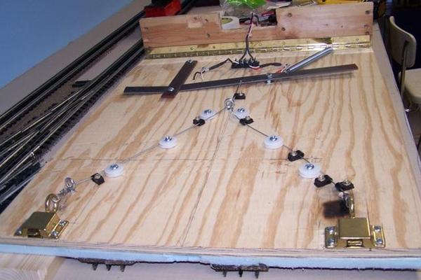
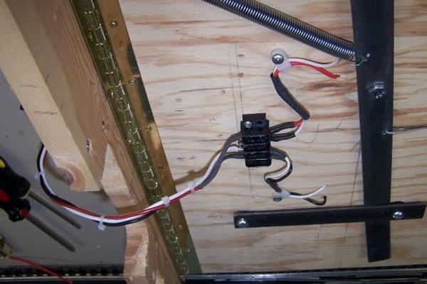
Sorry, I just found this question from you. Here is a photo of the unit wired. Note the wires running the length. Simple wire nuts, remember, my layout is temporary (Just took it down this week and stored it all.)
All the lifting, I never had a connection fail this Christmas. The two wires in the middle are for a tower on the top side. Oh yeah....move the chain from the middle at the bottom, to the outside. This is shown in the last picture.
Hope this helps you, Greg
(Oh yeah, think about making the track on each approach side of the bridge "dead" when the bridge is up. Here is a link to why you should! ![]() )
)
https://ogrforum.ogaugerr.com/d...04#12129987958270504
Attachments
Santa Fe VA, I ran a 10 gauge common ground underneath the track below the Benchwork. I also have four conductor trailer cable, two conductors are for the two mainlines and the other two are 12 volts for accessories and 14 volts for switches. The bridge is powered with flexible wires on the hinge end. I use Jim Barrett's protection system on both sides to remove power from 4' feet on each side when the gate is open. I have a separate protection relay and micro switch for each side so I don't have to run wires across the gap.
Ingenious fabrication work John and Greg.
Here are a few photos of my now 10 year old, "old-fashioned" Jim Barrett designed piano-hinged Drop Section when I had it removed, recycling it for the second time from a dismantled layout over to my little 9x16 round-the-room attic layout. In first photo it is removed and lying upside down. It shows the lever, and brake cable that triggers the transom catches. The second shows the "loop" where the wire run connects to the fixed layout. It has continued to work out well[with some "first aid"] in my very compressed space area. I need to reinstall power interuption lever switches or perhaps check on a more modern protection system..


