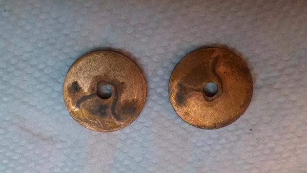
I've been working with Lionel Postwar whistle/horn relays for quite a few years now, but lately I've been realizing that I don't really understand how/why it works only with DC current. The e-units and switch machines have a similar coil in them, but they respond to AC (albeit they work with plungers). And you can convert them with rectifiers to work on DC to eliminate the AC buzz.  Greenberg has a section on relays and discusses the minimum DC voltage that gets them to work, but mentions that over 25 or so volts it will respond to  AC. Does it have to do with the fact that AC alternates it's current 60 times/ sec and therefore DC is a better way to make an electromagnet work? I also noticed that there are two copper discs at the base of the relay. I suspect they are there to be more than washers for the metal plate. They look a lot like rectifier discs.  But I'm just throwing ideas out. If anyone can jump in and explain how it works, it would be appreciated. 


-Roger

Original Post

Replies sorted oldest to newest

See this link.


From the link:


quote:


I passed this question along to our resident Lionel expert. Below is his answer:

Dave,  It has to do with Shaded-pole Relay theory.  Very basic explanation is that the is a copper ring on the relay core the effectively shorts the AC

magnetic component to keep the relay from picking up.  When a slight bit of DC is present, which is superimposed in the whistler control circuit, the shunt ring can't cause a magnetic short and thus the relay picks up.

Jim


Last edited by C W Burfle

I would use a bit of a different approach in explanation, compared to the "opposing" magnetic fields in the clip above.  Magnetic fields have the property that they store the energy required to build them, and the magnetic "lines of force" in the created field behave like rubber bands being stretched out at the field expands-- that is, the "lines of force" do not like to be confined close to each other, so magnetic fields do not like to be built.


So, with alternating current, the fine wire coil acts as a primary transformer coil, and the two copper ring blanks as a secondary coil which is shorted.  (This can be used to design the size of the copper "slugs," as they are sometimes called.)


With this arrangement, the magnetic field never builds at all when the coil is driven by an AC current.  A superimposed DC current, however, will close the contacts.


It's all in how you look at it, of course.  Obviously, the transformer action requires some sort of leakage field, and the iron core the relay helps in the magnetic circuit of the transformer effect.  I just find it easier to visualize this way.


--Frank

Originally Posted by M. Mitchell Marmel:

So how would one go about using a regular Radio Shack relay to replace the Lionel relay?

Taking your question at face-value, using the "solid-state" ERR circuit that GRJ mentions:


http://www.electricrr.com/Hobby/PWR-Ctlr/PWR.htm


replace the specified $5 triac SSR with a regular Radio Shack relay.  For example,  it appears RS has a 12V DC "regular" relay with 5 Amp contacts for $2 in-store.


http://comingsoon.radioshack.c...-relay/2750249.html#


A minor modification to the ERR circuit may be required, but considering the cost of buying the genuine original article, it may be worth the effort!

The above explanations of the Lionel relay's operation aren't correct.


First of all, this isn't a shaded-pole relay because it doesn't have two core sections.  A shaded-pole relay provides a second "hump" of magnetic flux that is out of time phase with the normal inductive flux.  (It is ahead in time of the main-winding flux because the shorting ring has almost no inductance.)  The shaded-pole relay, like a shaded-pole motor, is an attempt to have a two quadrature phases for a more continuous flux.


The above explanations of the Lionel relay don't mention the very essential steel crossbridge that is just above the two copper shorting rings.  The upper part of the relay works just fine as an inductor, with lots of flux in the steel core.  The flux travels up/down the core and then returns through the steel end/cross bridges and side pieces. 


What we don't want is any of that AC flux coming out the end of the core and pulling in the steel flapper on the bottom.  This flux is blocked by the shorting ring, essentially establishing a roadblock for flux coming down the core past the crossbridge, diverting the flux into the crossbridge.


For any DC flux, the shorting rings are invisible since the DC flux isn't varying.  Some of the DC flux squirts out the end of the core and pulls in the flapper.  (Some of the DC flux also is bypassed by the crossbridge, but enough makes it through to pull in the flapper.)

Originally Posted by stan2004:
Originally Posted by M. Mitchell Marmel:

So how would one go about using a regular Radio Shack relay to replace the Lionel relay?

Taking your question at face-value, using the "solid-state" ERR circuit that GRJ mentions:


http://www.electricrr.com/Hobby/PWR-Ctlr/PWR.htm


replace the specified $5 triac SSR with a regular Radio Shack relay.  For example,  it appears RS has a 12V DC "regular" relay with 5 Amp contacts for $2 in-store.


http://comingsoon.radioshack.c...-relay/2750249.html#


A minor modification to the ERR circuit may be required, but considering the cost of buying the genuine original article, it may be worth the effort!

The Lionel 8633-010 DC Offset circuit board(new number 610-8633-010), $7 from Lionel or $9 From The Train Tender, can also be used to activate that relay for a whistle or horn.

CW, from what I remember from Lenny Dean many years ago, the relay was used to ring the telephone bell when there was an incoming call. They were no longer made after the mid-sixties as telephones went solid state. That's about the time Lionel no longer used mechanical whistles and horns.

 We have all heard the stories about Lionel and Ives reversing units, but never about the DC relay. Probably because they came from an outside supplier.

Last edited by Chuck Sartor

I have just finished installing an ERR AC Commander in a 2344 F3.  One of the big things I did was to add a switcher power supply to power the horn.  I bought some of the inexpensive 3.3V-output switchers that can run on up to 40V input.  The outputs to the horn is fed through a diode, yielding about 2.6V at the horn for a good, loud "honk".


The switcher chip has an Enable/Disable pin that is normally grounded to operate.  I lifted that pin and added a pullup resistor and transistor to invert the logic so that the "high" signal from the AC Commander's Pin 3 on the sound connector can fire the horn.  Works great, and no more batteries or corrosion!!


The switcher has the advantage that it doesn't need to draw the full current of the horn from the track - acting like a stepdown transformer.  A linear regulator would pull the horn's full current.

No, I used a complete board with the LM3596-3.3, which is a 3 amp switcher.  The complete board was about $5, and I bought 3.  I just added a diode at the input and a diode at the output, plus 3 10K resistors and a 2N3904 for the inverter.

I like this scheme because the "trigger" is a low-power logic circuit and the regulator only runs while honking.


My next "science project" is to determine how much of the roller sparking on PW locos is due to the E-unit and whistle/horn relays' inductances.  I notice that this converted F3 has much less sparking without those relays present.  The Pullmor motors have gotten a bad rap in the past, but maybe they aren't the primary cause of the arcing.  (Yes, the new bypass capacitors across the brushes are another variable in this equation....)


quote:
I believe you're right Chuck.  The 90V ringing voltage was AC, but the holding voltage for the actual phone call was DC.  The AC wouldn't pick the relay, but it would ring the ringer.


This has me interested, so I went on line to try to find out more information. From what I have seen so far, there are no mechanical relays in telephones. So they were used in the switching equipment? Or maybe I just didn't find the right material.
This site seems to have a lot of information.


Last edited by C W Burfle

Earlier today I was rebuilding a whistle relay and ran into a rather rusty mounting screw for the contact stack that I'd like to replace.
None of the service station material I have on hand has a parts breakdown of the whistle relay. Just the entire unit.
But I did find the contact stack mounting screw in the Lionel engineering standards manual, volume I, section 3-G, page 1. It is part number WSR-42.

I browsed through the manual and saw a couple of other WSR parts that were probably for the relay, but not all of the components.

If Lionel was purchasing the relays from an outside vendor, why would they have some of the parts in their engineering book? I don't think that screw is used anywhere else.

Well, in theory only, I would say Lionel purchased the coil and bracket assembly from Bell Laboratories in bulk, and made the parts needed in house. (IE, the armature plate, the fiber insulators and contact lug stamping, like on the 3451 log dump car.) Maybe the coil assembly is what Lenny Dean meant that they came from Bell. (At least this what he told me many years ago.)

"Well, in theory only, I would say Lionel purchased the coil and bracket assembly from Bell Laboratories in bulk, and made the parts needed in house. (IE, the armature plate, the fiber insulators and contact lug stamping, like on the 3451 log dump car.) Maybe the coil assembly is what Lenny Dean meant that they came from Bell. (At least this what he told me many years ago.)"

Sorry, no.

Well Art, what do you have to back up your 'No'?  If what I was told is not true, then Mr. Dean was giving me a story. I can't say that I have ever heard about a patent Lionel had on this relay, so I would suspect they were purchased from an outside source. Same with the electronic receivers used with the electronic control set. I doubt the receivers were made in house.

"Well Art, what do you have to back up your 'No'?"

------------------

1. I am a retired Bell System employee with 30+ years service.  My jobs ranged from installer, repairman, switchman, lineman, splicer, circuit designer, engineer, security / safety supervisor and instructor.

2. I am also a student of the history of the Bell System and its policies, products and procedures.

3. Bell Labs is/was only the research arm of AT&T and it did not produce, or sell, any items.

4. Western Electric was the manufacturing and supply arm of the Bell System, and with very few exceptions, only sold to the parent company's (AT&T) regional Bell operating companies, or RBOC's. (What would become the so-called Baby Bells.) 

5. Western Electric sold communications equipment to the War Dept and its successor, the DoD. These items were exact duplicates of the products sold to the RBOC's, but instead of being stamped/branded "Bell System" they were simply branded Western Electric, and the part numbers and complete products had a "W" added to them to distinguish them as War Department items. 

6. Western Electric was prohibited by several court cases (called, euphemistically, "Consent Decrees") from selling to private industry. As an example, Western Electric Sound equipment for the movies was one such line of products that was spun off early in the history of the Western company. One major exception, which may be of some interest to us model railroaders, was the railway selector system, using the various 60-type line telephones, bells, selectors and transmitters.

See, for example, this instruction book. It's quite a large file, so open it with discretion if you have a slow connection.

http://doc.telephonecollectors...hing_Tel_Sys_OCR.pdf

7. I am familiar with all the types of relays that were produced by WE. If any specialized relays were used by the RBOC's or used in out-sourced assemblies, that were not made in-house (as 98% of the millions of parts were) they would have been marked with the "KS-xxxx" nomenclature. The KS stood for Kearny (NJ) Supply. The giant Kearny Works, covering hundreds of acres, was the national central manufacturing and supply source for all Bell System products.  Specialized or short order items were sourced from outside the System only when absolutely necessary, and always were coded with the KS- prefix. The System was compulsive about marking every last item with its number and revision letter(s). Some very small runs of specialized equipment (generally hand tools) were sourced from outside the System and carried the "AT-xxxx" series of nomenclature. The AT was shorthand for AT&T.

8. No central office, subscriber, carrier, military, or specialized product of which I can think ever used a relay that selectively responded to AC and DC, in the exact way that the Lionel whistle relay does.

9. In all my years of immersion into the history of telephony and into the hobby of train collecting, with a special interest in controls and signalling, I would have no doubt heard this story before, and it would have been the source of debate among my peers and colleagues. I have not heard it before today.

10. I have read, or at least perused, during the last 50 years of my life, every available Western Electric catalog starting with the extremely rare Catalog #1. I have never seen a reference to a relay of the type under discussion.

11. The relay, in concept, is not an especially clever design. It could not have been, nor can it now, be patented.

12. Lionel made most of its products in-house. The Bell System made most of its products in its house. In the event that Lionel did out-source the whistle relay, it would be surprising and inconsistent with what we have all been taught about Mr. Cowen's business model and personality, since Lionel prided itself, as did most industrial giants of the era, in being vertically integrated, just like the Bell System. It would have been ludicrous for Ma Bell to supply anything to Lionel. 

13. Concurrent with my career as a phone man, I have been a train operator, collector, and student of the electrical side of toy trains since 1954. I have designed and implemented circuitry for myself and some close friends. I have never considered that the whistle relay might have been out-sourced, and definitely never considered the far-fetched idea that they came from the Bell System.

14. Knowing, at least apocryphally, the man, the ego, and the personality of JLC, I would imagine that if the words Bell Labs, whistle relay and Lionel were ever to have been uttered in the same sentence, old Mr. Cowen would have spun it the other way 'round.

I am confident in my assertions. However, I am not dogmatic or stubborn. If anyone can supply a WE, AT- or KS- reference for the Lionel relay, I would be delighted to read it, and I will cordially admit my mistake.


Last edited by Arthur P. Bloom

Further to the other discussions from a few years ago, on this revived thread, regarding AC, DC, how the phones ring, and how the central office (CO) equipment responds, it's very simple, and does involve relays that differentiate between AC and DC. 

Telephone circuits use 48 Volts filtered (quiet) DC for talking. They use AC (generally 75 to 90 Volts, at 20 Hz) to ring the bells. The two are superimposed at the CO during the ringing portion of a call setup. The DC is blocked by a 0.5mFd capacitor in the telephone. The AC is passed through the capacitor, in series with the ringer motor.  When the telephone goes off-hook, the DC component is conducted through the talk circuit, and a ring-trip relay in the CO stops the ringing and completes the talk circuit through the CO equipment.

Some telephones have little relays in them, but they do not have anything to do with the concept of ring trip. They are for other signalling or voice switching features.

Last edited by Arthur P. Bloom

Here is something I find interesting:
The copper at the bottom of the whistle/horn relay call is usually described as being a ring. I found the part in the Lionel engineering book under a section titled "rings", but it did not look like a ring to this layman's eyes. The drawing looks more like a fender washer.  So I broke down a junk whistle relay that I was planning to cannibalize for the useable parts. The copper "rings" really do look like fender washers. See picture belowWSR-14

Attachments

Images (1)
  • WSR-14
Last edited by C W Burfle

Add Reply

Post

OGR Publishing, Inc., 1310 Eastside Centre Ct, Suite 6, Mountain Home, AR 72653
800-980-OGRR (6477)
www.ogaugerr.com

×
×
×
×
Link copied to your clipboard.
×
×