Hello,

I have been searching both the internet and this forum to determine what relay I would need to control track power on/off with an AIU.  I don't want to use the AIU directly because I seem to have a knack for blowing them out.   I don't fully understand relay speak so if someone could spell out exactly what I'm looking for it would be appreciated.

I want to be able to turn power on/off to sidings, roundhouse whisker tracks and yard tracks.  I understand that under DCS once you power a track you have to shut down/restart DCS engines, no problem with that.

Any help is much needed, thanks.

Original Post

Replies sorted oldest to newest

Cheryl,

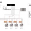
The below diagram is a bit hard to read, so I've also added the PowerPoint file if you can use it.  This was a modification to my TMCC setup I did a while back to see how DCS would work with relays.  Should be correct but I never set up it up.

To answer your question, I used 20/30amp Bosch style 12 volt SPDT relays from eBay powered by a separate 12 volt transformer.  Note:  Under AIU is should say "1 to Relay input 86", not 85.

TIU-AIU-RELAY-TRACK POWER

Attachments

Images (1)
  • TIU-AIU-RELAY-TRACK POWER
Files (1)
Last edited by CAPPilot
Charly posted:

Thanks for the info.  Question:  Do the relays always have an outside/aux power source?

They need coil power, so there has to be a power source.  If you select AC relays of the correct rating, you can run them from track power.  The power source seems to be such a simple issue that I didn't think it would be a problem.

Matt Makens posted:

Will passing the power through a relay have any negative effect of the DCS signal?

No more than passing it through a switch.

I recommend you sketch out a rough "to-scale" drawing of you layout showing the dimensions involved.   The "beauty" of relays is it allows you to use low-current signals to control (switch) high-current signals.  Not mentioned yet is the ability to then use thin/cheaper wiring for the control signals to activate the relays as opposed to running long lengths of thick/expensive wiring that carry the track-power. 

While you could "steal" track-power to provide the control current to activate the various relays, as GRJ says I'd go with a $2 external DC power supply (wall-wart).  This leaves max available track power from your transformers to drive your trains.

As GRJ shows, you can buy multi-relay modules from eBay for about $1 per relay.  These come in 1,2,4,8,16 relays per board for roughly $1 per relay.  This variety allows you to choose sizes that match the application to minimize the amount of high-current wiring.  For example, for roundhouse whiskers you could use a multi-channel relay module.  For a lone siding sitting out in the middle of nowhere you could use a single-channel relay module.  If using an AIU, this constrains your control signals to be centralized in increments of 10 (i.e., 10 accessory relays per AIU).  So, again, if you sketch out your layout the idea is to minimize the amount of high-current wiring relative to low-current wiring.  A related benefit goes to Matt's point of minimizing the length of track voltage wiring and any "negative effects" of running more wiring than needed as the track voltage wiring carries the DCS signal (while the low-voltage DC control signals do not).

s-l1600

Also, if you go with the eBay relay modules, most have so-called square-pin header connectors.  There are adapter cables/connectors which make it easier to work with these.  So if you go this route we can recommend how to attach to these connectors.

Attachments

Images (1)
  • s-l1600
Last edited by stan2004

SNRR Track Only

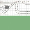
Here is the track plan.  The whisker tracks, the two sidings next to them, and the 3 ladder tracks are my primary goal.  These tracks all have engines sitting on them.  The rest of the sidings are possible future candidates.

I ask the questions only because I do not know and am curious.  Hope that's not a problem. 

Stan... glad you joined the discussion.  You were helping me at one time with a Lionel Itad, that I have since put aside as other matters became more important.  Someday I may come back to that, lol.

Thanks again guys for answering questions with enduring patience

Attachments

Images (1)
  • SNRR Track Only

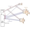
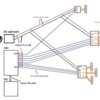
This is a classic case of measure-twice, cut-once.  That is, if you sketch out your relay wiring ahead of time you can skip the wiring clutter that is the inevitable consequence of an ad hoc wiring-as-you-go approach.  Here's a crude sketch illustrating a few ideas to consider (pic should be click-able to expand):

aiu relay module wiring

This uses the eBay ~$1-per-relay modules that GRJ identified and an external ~$2 DC wall-wart.  Each relay module, whether it be 1,2,4,8,etc. relays always receives DC power direct from the wall-wart.  This wiring carries a "medium" amount of current so something like #22 or #24 wire is fine.  Each module will have DC+ and DC- inputs for this power.  DC+ may be labeled VCC, and DC- may be labeled GND.

For every relay, there will be a control or trigger signal on the module.  So a 4 channel relay will have 4 control inputs typically labeled IN1...IN4 or CTRL1...CTRL4.  These signals come from the AIU. 

Let's just say we have 8 relays to control broken up into a 1-relay module, and 2 4-relay modules.  1 relay on the 2nd 4-relay module is unused and can be used later if you, say, add a new controlled siding.

Let's say we assign the 8 relays to ACC1 to ACC8 on the AIU.  When you select one of the Accessory outputs on the DCS Remote handheld and press the "ON" softkey, the AIU will send the control signal to the corresponding relay module which activates the physical relay.  These control signals (blue lines in pic) carry very little current so can be something like #28 wire.  #28 wire is the typical gauge used on those multi-conductor ribbon cables used in computers that you can often get really cheap surplus.  The relay under control then switches power to the controlled siding/whisker/spur.  By placing the relay physically close to the controlled track section this minimizes the length of high-current track-power wiring which is always a good thing.  Your track wiring is probably something like #14 or #16.

It sounds like you can control all your relays with a single AIU...but note that there is the question of where to physically locate the AIU.  You probably are using just the short 1 foot modular-plug phone cable between the TIU and AIU.  But in sketching out the wiring plan, you can imagine a scenario where maybe it would be easier/neater to physically locate the AIU further from the TIU using a longer modular phone cable.  Hard to say but this is part and parcel of doing the right thing before doing things right.

Another thought is whether you want some kind of visual feedback of the various relay positions.  The eBay relay modules have individual LED indicators showing if the relay is ON (a 4 channel relay module will have 4 LEDs).  Obviously these are on the board itself so if the board is attached under ground then it not as useful.  As you know (or may be doing right now) most layouts with a control panel with toggle switches to control block power have lights next to each toggle switch to indicate block is ON.  So if you want some kind of centralized panel with similar status indication, draw those connection into the diagram too.

Hopefully this is enough to move the ball forward a bit.

Attachments

Images (1)
  • aiu relay module wiring
gunrunnerjohn posted:

If  you want cheap relay modules that will handle 10A track power, look no farther than eBay.

eBay 262472832393 is an 8-channel 10A relay module for $4.97 shipped free.  You need a $2 5V power brick and a little wire, and you can control up to eight power districts from the AIU with no risk to your AIU.

Question to GRJ, I see you show a 5V relay module and 5V DC brick.  Why 5V instead of 12V?  There's no correct answer but I was thinking about other control modules that might apply to the layout (e.g., timers) for which 12V seems more common.  Yes, if a bunch of Arduino modules were hanging out 5V might make sense but I don't think that's in the immediate picture.

OK, great info.  I do have some DC wall worts with nothing to do, I'll have to check them for their power ratings.  I'm thinking of one in particular, an ex motorola phone charger.  I tried to use it to power a TIU for programming and it didn't quite cut the mustard.  Would it work for this type of thing?

Also, while snooping on the auction site I found this one and wondered what the 240V is referring to?


Last edited by Charly
Charly posted:

OK, great info.  I do have some DC wall worts with nothing to do, I'll have to check them for their power ratings.  I'm thinking of one in particular, an ex motorola phone charger.  I tried to use it to power a TIU for programming and it didn't quite cut the mustard.  Would it work for this type of thing?

Also, while snooping on the auction site I found this one and wondered what the 240V is referring to?


If you ordered the relay modules GRJ suggested you need a source of 5V DC.   If you have a wall-wart meant to power a USB hub or some similar computer/PC type device you may have such a widget.  As you say you need to check the power ratings to see if it can support driving (up to) 8 relays plus attendant circuitry (like the on-board LEDs and such).  The label on the wall wart should tell you the DC voltage and current capability.  I'd look for one with current of, say, 1 Amp = 1000 mA.   While you can buy a $1 eBay module that converts one DC voltage to another, GRJ points out you can get a 5V wall-wart for $2 so I'd just do that if you don't have a wall wart that directly puts out 5V DC.

The 240V in your linked item refers to how many volts the relays can switch.  You only need to switch 20V (whatever your track voltage) so that product is more than capable of handling the voltage.

An alternate approach to using relays for block control:

My DCS system wiring:

To avoid any problems with the TIU signal to each track (block) the TIU is wired in "Passive Mode".  As a result the track voltage is provided by my Z-4000 transformer entirely bypassing the TIU. (No input connections to the TIU are required).

My system applies track voltage using separate 12vdc relays which are operated via my AIU system. Wiring to the track is protected by separate circuit breakers and TVS DIODES (Transient Voltage Suppressors) for EACH block circuit output connection. As a result a short circuit in any block connection is individually protected so that a loss of power to the other blocks is not affected.  Wiring to each block uses 16 gauge wire.

DCS signal wiring:  All wiring from the TIU to each block uses 22 gauge wire.  Each connection from the TIU output bypasses the block relay circuit entirely and is permanently wired to the center rail.  Also wiring to each block from the TIU uses a series connected 560 ohm isolating resistor. In addition the TIU OUTPUT is protected using a TVS diode.

Note: The maximum current in the wiring from the TIU to the track is 40 miiliamperes so no fuses are necessary to protect the TIU when using  the TIU Passive control wiring scheme.

The circuit breaker panel shown includes an individual resettable circuit breaker and a TVS Diode for each block circuit output.

BLOCK CIRCUIT BREAKER BOX 004


Attachments

Images (1)
  • BLOCK CIRCUIT BREAKER BOX 004
Last edited by pro hobby

The Altronix RB610 appears to have screw-terminals for the control inputs whereas the eBay module uses square-pins that can be a nuisance to deal with.  Of course at $4-5 per relay (vs. about $1 per eBay relay) you can buy a lot of screw-terminal blocks or other wiring accessories with the money you "save" on the relay cost. 

What's also curious is you can order the RB610 from Office Depot of all places!

Actually, the one I ordered is this, and I got two, which just covers the 15 possible sections of track I wish to power off/on.


Brand new and high quality

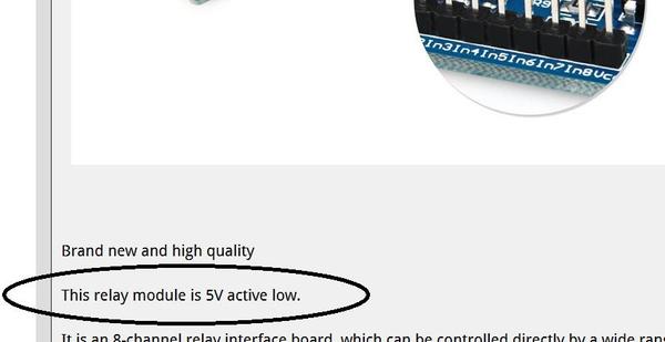
This relay module is 5V active low.

It is an 8-channel relay interface board, which can be controlled directly by a wide range of microcontrollers such as Arduino, AVR, PIC, ARM, PLC, etc.

It is also able to control various appliances and other equipments with large current.

Relay output maximum contact is AC250V 10A and DC30V 10A.

Standard interface can be directly connected with microcontrollers.

Red working status indicator lights are conducive to the safe use.

Widely used for all MCU control, industrial sector, PLC control, smart home control.


Specifications:

Working voltage: 5V

Channel: 8 channel

Item size: 13.5x5.5x1.6cm

Weight: 109g


Package includes:

1 x 8 Channel Relay Module

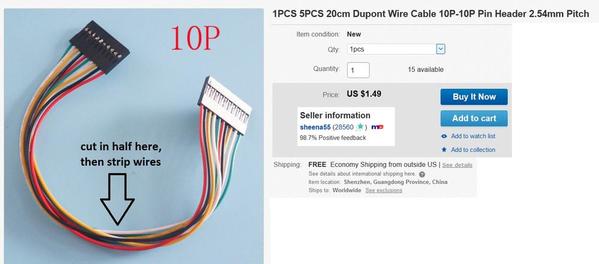
I think what GRJ is referring to by cable assembly, and what I also recommend would be something like the following.

10p header cable

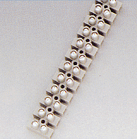
That 8-relay module appears to have a 10-pin header with pins spaced 2.54mm (0.1").  So, for example, one of the above cables could be cut in half and wires stripped.  The connector side obviously just plugs right on to the relay module header.  The stripped wires could then be plugged into a terminal strip/barrier to "convert" the flying wires to screw-terminals. 

screw terminal strip ebay cheap

Agreed that's an extra step or two but no soldering and should save some $ when all's said and done...

P.S. The cable shown has a 10-pin header, but these come in different sizes.  For example, a 4-channel relay module probably has a 6-pin header so a less-expensive 6-pin cable could be used and cut-in-half to wire up two 4-channel modules.

Attachments

Images (2)
  • 10p header cable
  • screw terminal strip ebay cheap
Last edited by stan2004

I wonder how many shorts a relay can break compared to a toggle switch of equal capacity????  One problem with using a relay module is that if one relay fails, the entire set may have to be replaced.

Charly, some months ago, in threads regarding LED lighting, GRJ and I made mention of AC/DC buck converters, 1-24VAC in, adjustable DC out, real cheap, maybe $3???  They can be adjusted down to 5 volts.  I use them for powering relays, set to 12VDC output to match my relays, and set to 4.5 volts for powering Menards-lit buildings.

RJR posted:

I wonder how many shorts a relay can break compared to a toggle switch of equal capacity????  One problem with using a relay module is that if one relay fails, the entire set may have to be replaced.

Charly, some months ago, in threads regarding LED lighting, GRJ and I made mention of AC/DC buck converters, 1-24VAC in, adjustable DC out, real cheap, maybe $3???  They can be adjusted down to 5 volts.  I use them for powering relays, set to 12VDC output to match my relays, and set to 4.5 volts for powering Menards-lit buildings.

Hmmmmmmmmm.  I understand your comment, but am rather committed at this point.  My BF has about a dozen 12volt dc power supplies he acquired from somewhere, who only knows, and has given me 3 for my lights, so I'm good there.  I just want to shut off sidings, stubs and round house whiskers until I'm ready to power up something on those tracks.  Occasionally I have a derailment short that sets everybody off and with 30 or more engines on live track it can be a pretty intense few seconds .

gunrunnerjohn posted:

DC 5V 2A/2000mah AC Power Adapter Wall Charger

eBay: 171854362635, $2.78 with free shipping.


I finally did find one very similar to this and I was able to get two for under $4.00 dollars.  But thank you for responding, it's great to know you guys are willing to help out a newbie like me

Was just reviewing this thread and noticed the relay module you purchased is "active low".  This means to activate a particular relay, you must apply a "low" or the "-" voltage to the IN pin. 

relay active hi or lo

Some relay modules are "active high" which is what I assumed you had when I previously drew the hookup diagram.  No problem - here's a revised diagram. You attach either "+" or "-" from the DC wall-wart to the daisy-chained AIU input.  Since your relay module is "active low", you attach to "-".

aiu%20relay%20module%20wiring


Attachments

Images (2)
  • relay active hi or lo
  • aiu%20relay%20module%20wiring
Charly posted:

Actually, the one I ordered is this, and I got two, which just covers the 15 possible sections of track I wish to power off/on.


Brand new and high quality

This relay module is 5V active low.

It is an 8-channel relay interface board, which can be controlled directly by a wide range of microcontrollers such as Arduino, AVR, PIC, ARM, PLC, etc.

It is also able to control various appliances and other equipments with large current.

Relay output maximum contact is AC250V 10A and DC30V 10A.

Standard interface can be directly connected with microcontrollers.

Red working status indicator lights are conducive to the safe use.

Widely used for all MCU control, industrial sector, PLC control, smart home control.

One more question... 

I have power supplies, header cables and the units.  What I'm wondering is what the little yellow jumper is for and do I need to tie both those pins to hot when I wire up the power supply?

Thanks

Charly posted:
 

I have power supplies, header cables and the units.  What I'm wondering is what the little yellow jumper is for and do I need to tie both those pins to hot when I wire up the power supply?

The yellow jumper allows you to connect/separate the relay power supply from the control signal power supply.  In your application you want the two supplies to be the same.  Hence, leave the jumper in place.  Your board will get its "hot" 5V DC power from the main header connector on the pin labeled "VCC" which is the rightmost pin in the photo.

stan2004 posted:
Charly posted:
 

I have power supplies, header cables and the units.  What I'm wondering is what the little yellow jumper is for and do I need to tie both those pins to hot when I wire up the power supply?

The yellow jumper allows you to connect/separate the relay power supply from the control signal power supply.  In your application you want the two supplies to be the same.  Hence, leave the jumper in place.  Your board will get its "hot" 5V DC power from the main header connector on the pin labeled "VCC" which is the rightmost pin in the photo.

Do I connect the ground to the main header marked gnd then, also?

Where can I find the connectors with wires attached to them.  I’ve been looking but I’m not even clear about what they would be called.
 
stan2004 posted:

I recommend you sketch out a rough "to-scale" drawing of you layout showing the dimensions involved.   The "beauty" of relays is it allows you to use low-current signals to control (switch) high-current signals.  Not mentioned yet is the ability to then use thin/cheaper wiring for the control signals to activate the relays as opposed to running long lengths of thick/expensive wiring that carry the track-power. 

While you could "steal" track-power to provide the control current to activate the various relays, as GRJ says I'd go with a $2 external DC power supply (wall-wart).  This leaves max available track power from your transformers to drive your trains.

As GRJ shows, you can buy multi-relay modules from eBay for about $1 per relay.  These come in 1,2,4,8,16 relays per board for roughly $1 per relay.  This variety allows you to choose sizes that match the application to minimize the amount of high-current wiring.  For example, for roundhouse whiskers you could use a multi-channel relay module.  For a lone siding sitting out in the middle of nowhere you could use a single-channel relay module.  If using an AIU, this constrains your control signals to be centralized in increments of 10 (i.e., 10 accessory relays per AIU).  So, again, if you sketch out your layout the idea is to minimize the amount of high-current wiring relative to low-current wiring.  A related benefit goes to Matt's point of minimizing the length of track voltage wiring and any "negative effects" of running more wiring than needed as the track voltage wiring carries the DCS signal (while the low-voltage DC control signals do not).

s-l1600

Also, if you go with the eBay relay modules, most have so-called square-pin header connectors.  There are adapter cables/connectors which make it easier to work with these.  So if you go this route we can recommend how to attach to these connectors.


The connector is a so-called 2.54mm (0.1") square-pin header.  You buy individual female crimp sockets, then use a crimp tool to attach to a wire, then insert crimped wire into a housing with desired number of positions/contacts.   Housings come in 1, 2, 3, 4, 5, etc. positions.  The relay module shown above has a 6 pin header so would require crimping 6 wires and inserting them into a 6P housing.

header crimps and housing examples

header crimps and 6P housing

Crimps should be maybe a penny a piece and you'd buy them by the hundreds.  Housings may be 25 cents each or so.  A crimp tool might be $10 (?) though you might be able to "get by" with needle-nose pliers - your mileage may vary!

I'm skeptical you would be able to purchase pre-crimped wires with lengths of 10 feet (or whatever) to reach from a relay module back to a control panel. 

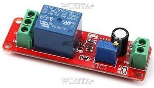
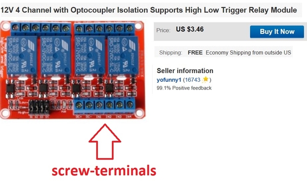
That said, I'd suggest using a relay module with screw-terminal inputs (rather than the 2.54mm header).  Here's a 4 channel module for less than $1 per relay.  

12v 4 channel relay module with screw terminal inputs

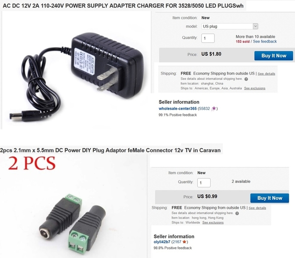
Note: this module operates from 12V so you'd use a 12V DC wall-wart; I see the previous example used a 5V relay module and a 5V DC wall-wart.  I saw on eBay they also have 5V relay modules with screw-terminal inputs.  It's just I have the above 12V channel module.  A 12V DC wall-wart that can power dozens of relay channels is about $2.  

12v dc wall-wart and screw-terminal - december 2017 ebay

You can also buy a handy adapter that converts the barrel-coax to screw-terminals so you don't have to splice the wall-wart output connector.

adapter


Attachments

Images (5)
  • header crimps and housing examples
  • header crimps and 6P housing
  • 12v 4 channel relay module with screw terminal inputs
  • 12v dc wall-wart and screw-terminal - december 2017 ebay
  • adapter

Add Reply

Post
The DCS Forum is sponsored by

OGR Publishing, Inc., 1310 Eastside Centre Ct, Suite 6, Mountain Home, AR 72653
800-980-OGRR (6477)
www.ogaugerr.com

×
×
×
×
Link copied to your clipboard.
×
×