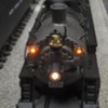
First off some brief history and inspiration for this project. I have a couple of early PS2 MTH USRA Mikados. The first made in 2001 has PS2 5 Volt and wired tether and the second made in 2005 has PS2 3 volt and also a wired tether. MTH has made two subsequent NYC Mikes in 2007 with PS2 and wireless tether and finally in 2016 with PS3 and wireless tether. With each release MTH has made minor upgrades in detail and electronics.

The first 2001 issue came with pilot air hoses and rope pulls for the bell and whistle. The 2005 issue added cab curtains. The two with wireless tethers added engine decks, now that the wired tether was gone.

I have been gradually going through my early MTH steam (and other steam) and adding cab curtains and decks after straightening the tethers.

This is the 2005 engine showing the pilot air lines, lift bar with chain, and cab curtains (all from the factory) and engine deck which I added after straightening the tether. The drawbar was also replaced with a shorter one. (easy on a wired tether engine)

MTH_Mike_Front

MTH_Mike_Side

The K-Line engine came without pilot air lines, rope pulls, cab decks or curtains. To add the rope pull the bell was changed out to one with a lever. Yet to be replaced is a whistle with lever for the rope pull. Cab Curtains and deck were added and shorter drawbar installed. Coupling is now closer than the fitted drawbar would allow. Not a problem as this will get run on the club layout with 072 minimum curves.

K_line_Mike_Front

K-Line_Mike_F-Side

K_line_Mike_Rside

This engine has been upgraded to K-Line Cruise. Still to be done a fan smoke unit. Three Lionel Mikes have yet to get this treatment including a Legacy USRA Light and Heavy. Their detail is the same as the stock K-Line. Parts to do this cost under 10 bucks with the bell being the expensive part.

Hopefully someone at Lionel will read this and add these details to their next production model.

Pete


Attachments

Images (5)
  • MTH_Mike_Front
  • MTH_Mike_Side
  • K_line_Mike_Front
  • K-Line_Mike_F-Side
  • K_line_Mike_Rside
Last edited by Norton
Original Post

Replies sorted oldest to newest

You never cease to amaze me with your skills, Pete. Keep up the good work.

The tender truck chains that MTH has done since 2004 is also something I'd love to see Lionel do on their steamers in the future.

I passed on the new Legacy Light Mikes - at least for now - but I'll keep these tips in mind should I get one or the less expensive, previously released Heavy Mikes.


Norton posted:

Jon Z gave us the key. I am using an RCDR programed with the same number as the R2LC. The bell coil was replaced with a micro gear motor. This couldn't have been done with the coil. Also I was using a Cab1 to control it.

Pete

I'm still not clear on synchronizing with the bell sound.  I get the RCDR for receiving the TMCC signal, but what board is actually driving the motor?

OK, that makes sense.  How did you connect that motor to the bell board?  It works really well, and a lot of the possible victims I have use a similar bell design.  I don't have too many with the bell on the boiler where the magnet coil would work.  Is it really as simple as connecting that little gear motor?  What determines when it stops for each end of the bell swing?

I thought I was going to have to process the bell board signal to drive the motor. In fact its nearly perfect as is. The motor is rated for 6 volts and 90 rpm. The bell board puts out about 7 volts. There needs to be a pot to adjust the speed to match the bell sound. 

In a TMCC engine where an RCDR is needed you have make sure you address it as a TMCC engine. With a Cab1 no problem but with a Cab2 a quick hit on the bell button gives one ring but  the R2LC keeps the ringing  sound until the bell button is hit again. 

Application of this is pretty much limited to medium size TMCC  engines or tenders. Legacy engines might be a little smaller as only the bell board is needed.

Here is another video I made before installing the motor in the engine. My crankshaft is just a 2-56 nylon nut press fit on the motor shaft.


Pete

Attachments

Videos (1)
trim.BCB2E639-DAD7-41AB-A8AD-A2865A02BD86
Last edited by Norton

Bruk, the pot is wired as a variable resistor so I am increasing the resistance to slow it down, not as a true potentiometer to divide the voltage. I made a board with a full wave bridge, 20uf tantalum cap and the pot placed between the bell board and motor. I don't think the bridge is needed but kept it in as I had the room. The cap is mainly to tone down the noise I was seeing on the bell board drive signal. Again likely optional if space is critical.

I want to point out again, credit for this idea goes to Laurie Mclean and Jon Z and Lionel tech for producing what is essentually a decoder that transforms the bell signal to a DC level. I just combined these two ideas.

For those who have not discovered Laurie's videos here a few. Next on my project list is the working fireman.

They basically all work on the same principle of a crankshaft turning rotary motion into linear motion. The mechanics are fairly straightforward. Its triggering this motion remotely thats been made a problem by being unable to add custom functions to Lionel's and MTH's handhelds. 

Last edited by Norton
Norton posted:

Bruk, the pot is wired as a variable resistor so I am increasing the resistance to slow it down, not as a true potentiometer to divide the voltage. I made a board with a full wave bridge, 20uf tantalum cap and the pot placed between the bell board and motor. I don't think the bridge is needed but kept it in as I had the room. The cap is mainly to tone down the noise I was seeing on the bell board drive signal. Again likely optional if space is critical.

I want to point out again, credit for this idea goes to Laurie Mclean and Jon Z and Lionel tech for producing what is essentially a decoder that transforms the bell signal to a DC level. I just combined these two ideas.

For those who have not discovered Laurie's videos here a few. Next on my project list is the working fireman.

They basically all work on the same principle of a crankshaft turning rotary motion into linear motion. The mechanics are fairly straightforward. Its triggering this motion remotely thats been made a problem by being unable to add custom functions to Lionel's and MTH's handhelds. 


This is why I'm converting my items to DCC easier for these custom installs.  I still mess around with Lionel's electronics, but I don't like the closed system. DCS is basically DCC. So Id rather convert over to actual DCC.

image

John, here is pic of the boards taken during developement. Ignore the big cap on the board on the right.

From left to right, RCDR, Bell Board, Pot, motor.

Bell board output in this case goes to the bridge but could go directly to the pot or even motor if you didn't need to adjust the speed.

In this case polarity at the motor doesn't matter.

Pete 

Attachments

Images (1)
  • image
Last edited by Norton

Sorry, I missed your main point. I expected the bell board to change polarity and thats why I added the bridge but in fact its just a DC level on and off. Maybe the bell is located over one end of the bell coil and reverses when the DC Level is zero. Never looked at that.

The cap was there to solder the motor wires to. It was taken out and replaced with a connector.

Right now the engine and tender and back apart as I look for a better solution for a tether.

Pete

Last edited by Norton
prrhorseshoecurve posted:

Can this work conventionally with hitting the Bell button on the transformer or does this have to be TMCC/ Legacy?

I think Jon Z said it won't work in conventional but it might not be too hard to design a circuit that responds to the DC offset and start the motor. Mines apart now so I can't test that option.

Pete

So Pete explain something to me, Does the Bell Board need a DC offset to trigger its function?  Or is it controlled by both Conventional DC offset or a Legacy/TMCC command signal for bell?

Does the RCDR one shot a DC offset on the Bell Command?

I guess I am wondering my you need the Bell Board?  Or why you need the RCDR.

Can the RCDR DC Offset Latch a small board to provide the 5V to drive motor?  Second Press of Bell turns latch off.  Your at 3 boards anyway, so it seems possible a simple board to replicate what the Bell board does replaces the bell board.   Or why is the RCDR needed?  G

G, The bell board works off serial 9 bit data, not a DC offset. I doesn't work in conventional. The RCDR is there to provide the 9 bit data. If you used this in a legacy engine you wouldn't need the RCDR, only the Bell Board. the Bell board is basically a decoder that takes the bell signal and outputs a 7V DC level to energize the bell coil instead of an audio board. I am using the motor instead of a bell coil.

I used the RCDR because I wanted to try this on a TMCC engine. The original R2LC still provides the signal to the RS4 board and the RCDR to the Bell board. As long as you address the RCDR as a TMCC engine the bell movement and sound stay in sync. If you address the RCDR as a Legacy engine then the bell will sound after the movement stops

Last edited by Norton

John, note on the thread where the member blew up his bell board that his version did not have Legacy common, only frame ground. maybe that would work with an R4LC?? Something worth checking when you get all of your boards. I know on the bell board I am using it did require Legacy common that the RCDR did provide.

BTW I was also wondering if the requirement that the bell board would only work with Legacy is because of the signal common requirement or the 9 bit data requirement?

Pete

Hudson J1e posted:

Wow! Phenomenal job on the swinging bell. It looks extremely realistic. 

Pete, I have always liked the idea of straightening out MTH tethers is there a thread somewhere showing how you did it? 

BTW, your ballast also looks very realistic. 

Thanks Phil. 

I started out replacing the right angle tether with a straight MTH one. Then when these became harder to come by I simply straigtened the right angle one documented in these two threads. The straight ones are more elegant but the modified right angle ones are more economical like $0.00.

https://ogrforum.ogaugerr.com/...ting-older-mth-steam

https://ogrforum.ogaugerr.com/...ghtening-mth-tethers


Pete

Last edited by Norton

Add Reply

Post

OGR Publishing, Inc., 1310 Eastside Centre Ct, Suite 6, Mountain Home, AR 72653
800-980-OGRR (6477)
www.ogaugerr.com

×
×
×
×
Link copied to your clipboard.
×
×