Norton posted:

John, note on the thread where the member blew up his bell board that his version did not have Legacy common, only frame ground. maybe that would work with an R4LC?? Something worth checking when you get all of your boards. I know on the bell board I am using it did require Legacy common that the RCDR did provide.

BTW I was also wondering if the requirement that the bell board would only work with Legacy is because of the signal common requirement or the 9 bit data requirement?

Pete

Pete, I see there are a couple versions of the bell board, and I suspect that could be a difference.  I'm going to have to trace these out and see how the serial data is received.

I'm almost positive Legacy only issue is the 9-bit data, several older Legacy models have the bell board with the R4LC and DC ground common with frame ground.  I just wonder if the newer version of the board changes the input circuit for the serial data.  If there's an opto-isolator on the input, it could work for both, that's what the Legacy-Lite RS board has.

This is the circuit that's on the old ERR Sound Converter, note that it supplies both isolated and non-isolated serial data capability.  Could be all of these have isolated serial data, I'll have to check.

Attachments

Images (1)
  • mceclip0
gunrunnerjohn posted:

I'm curious on the RCDR equipped Legacy if we'll have an issue with the serial data ground not being frame ground.  For TMCC and early Legacy with the R4LC, frame ground and DC ground are the same.

I asked the question a while back on the BEMC boards when I installed it in my 3rd Rail loco/updating the Diagrams for BEMC and John Route responded with....

“The Ret is the serial date return reference.  It provides the same ground ref as the source of the serial signal.  This allows some boards to use 1/2 wave AC (required on receivers) to connect to full wave AC rectification powered PCBs like the BEMC.”

When installing those electronics I ran into a issue where I did not ground out the RET pin on the BEMC board to the frame. This was causing the board to not see the serial data clearly from the RCDR.


Dunno if this would answer your question John....

Last edited by Bruk
Norton posted:

I don't think it matters what Legacy RCDR you use. I think mine came from the Legacy 0-8-0. You just need a radio board that outputs 9 bit serial. A TMCC version will not run a bell board. I didn't know there were TMCC RCDRs. If there are they won't work.

Pete

It only matters on what you are hooking up to it. Serial data is the same across the board....

I also used a 0-8-0 RCDR in my 3rd Rail conversion and I was going to hook up the backup light through the RCDR (less wiring than doing it through the RS-Lite/LTC1)

I had wired it like they had done in the auxilary tenders (as i show in the diagrams) and got nothing from the outputs. I did get coupler function but no lighting. I tried another board from a Hiesler did the same thing. 

@Norton

Thanks for all your help!

With your tutelage I was able to swap the bell yokes from the K-Line Berkshire to the Mike. Photos of Berkshires didn’t show a lever arm for the bells, but the model did. With a razor saw and patience, and cold sweats and shaking hands, I was able to slit the yoke and pry up the casting to get the yoke in the saddle. I say this every time, but never again!

before:

35D14967-FA5A-442D-B6F7-BF6A7E8EB61E14A86F06-C16F-4397-AA62-2FA118922A4DF5F21322-8247-4BBE-9B6C-C7097B3FE357

and after...

FF7D8057-7A05-4ADD-A6D3-66BB55E6EFE5C57CC492-B6B4-48BE-B254-540466E9F3D5DCF6D08F-FAB4-472E-8127-F3F1CB501884C1A55D06-B469-41FF-9AF1-4C2E8C7E999Dthanks so much!

-Mario

Attachments

Images (7)
  • 35D14967-FA5A-442D-B6F7-BF6A7E8EB61E
  • 14A86F06-C16F-4397-AA62-2FA118922A4D
  • F5F21322-8247-4BBE-9B6C-C7097B3FE357
  • FF7D8057-7A05-4ADD-A6D3-66BB55E6EFE5
  • C57CC492-B6B4-48BE-B254-540466E9F3D5
  • DCF6D08F-FAB4-472E-8127-F3F1CB501884
  • C1A55D06-B469-41FF-9AF1-4C2E8C7E999D

Hey Pete,

This is my first time chatting with you and I really have great intereste in this post. I will continue to follow it to it's end because I'm fascinated with the bell project as well as the fireman shoveling the coal. I was a fireman in New Hope Pennsylvania at the New Hope & Ivyland R.R. on #40, a consolidation steam loco and I loved it. It was a part time gig for me. I was also a member of the Raritan Valley Hi-Railers-a modular "O" Gauge group in N.J. plus The N.J. Hi-Railers, so this has been a passion for me, plus it offsets the live steam days also. Hope you share all of the info with us!  Thanks

Steam Forever

        John

Hey John, I haven’t gotten around to the animated figures yet but have plans to use some new found devices to trigger movement. Others are planning similar projects. Stay tuned. Currently involved in other projects so it may be awhile. I did add a swinging bell to a Legacy engine but that was pretty straightforward. Just get a bell board and bell coil and feed it serial data.

Pete

@Norton posted:

First off some brief history and inspiration for this project. I have a couple of early PS2 MTH USRA Mikados. The first made in 2001 has PS2 5 Volt and wired tether and the second made in 2005 has PS2 3 volt and also a wired tether. MTH has made two subsequent NYC Mikes in 2007 with PS2 and wireless tether and finally in 2016 with PS3 and wireless tether. With each release MTH has made minor upgrades in detail and electronics.

The first 2001 issue came with pilot air hoses and rope pulls for the bell and whistle. The 2005 issue added cab curtains. The two with wireless tethers added engine decks, now that the wired tether was gone.

I have been gradually going through my early MTH steam (and other steam) and adding cab curtains and decks after straightening the tethers.

This is the 2005 engine showing the pilot air lines, lift bar with chain, and cab curtains (all from the factory) and engine deck which I added after straightening the tether. The drawbar was also replaced with a shorter one. (easy on a wired tether engine)

MTH_Mike_Front

MTH_Mike_Side

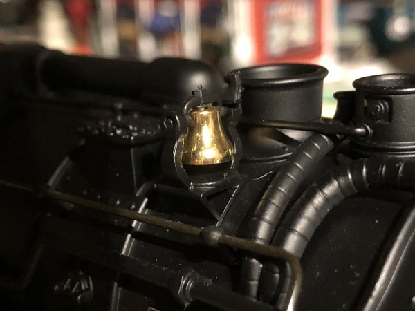
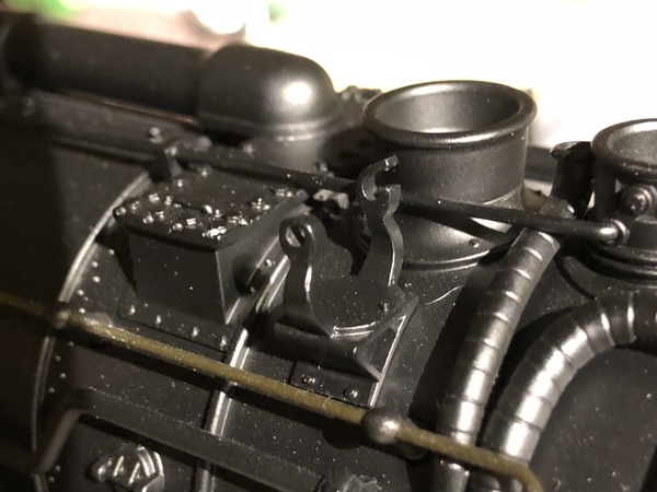
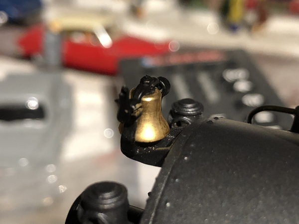
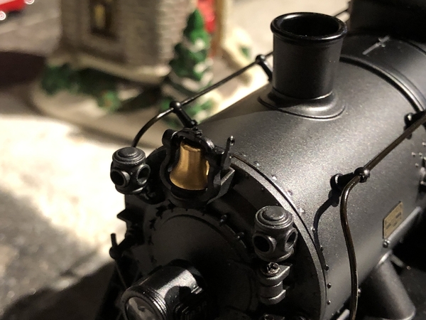
The K-Line engine came without pilot air lines, rope pulls, cab decks or curtains. To add the rope pull the bell was changed out to one with a lever. Yet to be replaced is a whistle with lever for the rope pull. Cab Curtains and deck were added and shorter drawbar installed. Coupling is now closer than the fitted drawbar would allow. Not a problem as this will get run on the club layout with 072 minimum curves.

K_line_Mike_Front

K-Line_Mike_F-Side

K_line_Mike_Rside

This engine has been upgraded to K-Line Cruise. Still to be done a fan smoke unit. Three Lionel Mikes have yet to get this treatment including a Legacy USRA Light and Heavy. Their detail is the same as the stock K-Line. Parts to do this cost under 10 bucks with the bell being the expensive part.

Hopefully someone at Lionel will read this and add these details to their next production model.

Pete


Ta

I just saw your video. This is absolutely amazing. Well done. Remind me of the time when I first saw the Lionell are 27 Subway when the doors opened I **** near wet my pants. Just an amazing feat.

Last edited by ThatGuy

That should work. Realize there are different RCDRs but the connections are similar and all should work. They are only used to provide Legacy serial data. I added a big cap across the motor to smooth the square wave that the bell board puts out. Also a 100 ohm pot might be a better choice. I will have to check motor resistance but suspect its under 30 ohms.
I will mention for others that the RCDR is only needed for TMCC engines.

Pete

It is a small motor with a gear head to slow it down.  Pete forced a nylon washer on the shaft and drilled a small eccentric hole in it for the fine piano wire.  It acts as a cam to give the back and forth motion.  See his video around halfway down the first page of the thread.

Bob

Last edited by RRDOC

This is a very interesting thread.

But where I am confused is how is the micro motor running? Is this a mini stepper motor? Is the motor running continuous and one needs to build some sort of gear reduction/arm pulling mech/clutch mech to get the back and fourth swinging motion of the bell?

Inquiring minds want to know!

Curve, this is the video that was the inspiration. Only difference is instead of using a DCC decoder, I used the Lionel Bell Board which can be viewed as a Legacy decoder.

Pete

Last edited by Norton

Here is the revised schematic for Pete's swinging bell circuit .

Parts:

Lionel cs-691RCDR101-p RCDR (TMCC only, with Legacy Locos, use existing RCDR)

Lionel cs-691CDV1101-p Bell Coil Drive PCB

SPST or SPDT Mini Slide Switch

100 Ohm 1/2 watt trimmer potentiometer

470uF 16v Electrolytic Capacitor

700:1 Sub-Micro Plastic Planetary Gearmotor 6Dx21L mm


Swinging Bell Circuit

Bob

Attachments

Images (1)
  • Swinging Bell Circuit
Last edited by RRDOC

Add Reply

Post

OGR Publishing, Inc., 1310 Eastside Centre Ct, Suite 6, Mountain Home, AR 72653
800-980-OGRR (6477)
www.ogaugerr.com

×
×
×
×
Link copied to your clipboard.
×
×