gunrunnerjohn posted:

Adrian, I do foresee a much larger issue with switching the Legacy signal.  Since any large layout will have multiple TIU's and multiple channels, you need to have multiple switches to manage the Legacy signal interruption.  However, you can only have one Legacy signal source in the entire layout, so there's the issue of a major disconnect between this unit and the TMCC Buffer.  The only way I see this working is somehow having all these interrupter switches feeding a common switch that turns off the Legacy signal.  Obviously, you are then dealing with the propagation delay as usually the TIU's are scattered all over the layout with a really large layout.

Until we can somehow address that issue, I don't see how this can work.  Maybe balancing the Legacy signal between the center rails and the outside rails is a better bet after all.

I'm very aware of this and have been thinking about it already actually.

Right now I'm building one of these for the SD3R folks who have 1 TIU right next to the legacy base. The board I have connects to the 4 TIU outputs and "ORs" them together to run the switch.

I'm thinking even if you chop off the better part of the first DCS packet in a sequence (like 1-10us) the DCS command will only have to repeat 1 extra time before everything is communicating within the hole and the decoder is clean.  At our AGHR club we probably have a good 200-300 ft between TIUs so that's almost 1us of delay right there. Once I have the nice boards back I was going to try to wire them across the club with a remotely located switch and see how it performs. Maybe the initial latency is not as critical as we think. Testing should answer this...

Balancing the center and outer rail isn't so easy either.  After thinking a bit.... while the outer rail is often a single node in a layout, the center rail is usually broken up into blocks, so you'd need a lot of copies of whatever circuitry is doing the balancing. You need to distribute the legacy signal to all of them, and they all need a connection to earth ground as a reference. If you have earth ground connections all over the layout to support this, the cap may go up a lot and impact the legacy/tmcc performance. Sound hard...

Both options sound hard Adrian.   I was also mulling over balancing the center rail and I came to the same conclusion you did.  The only thing that occurs to me is some sort of notch filter to pass the 455khz but block the other frequencies.  As you say, you need one for each TIU channel block, so that's sort of ugly as well.  As far as affecting Legacy performance, that's what the TMCC Buffer is for.

The single-TIU solution is fully built and bench tested. I just need to drop it in a project box, get a wall adapter to power it, and it's good to go.

SD3R_DCS_LEG_PCB

SD3R_DCS_LEG_PCB2

The plan is to stick it into our club layout on a TIU somewhere and see if any legacy users notice something happened (it's a double blind test). If they don't notice anything we have an answer for at least the single TIU case. I'll post layout results as I get them.

-->The idea is after I prove it's okay in our club, I'll box it up and send it down to the SD3R club. They have a single TIU layout and had the legacy-DCS issue in the first place.

Attachments

Images (2)
  • SD3R_DCS_LEG_PCB
  • SD3R_DCS_LEG_PCB2
Last edited by Adrian!
gunrunnerjohn posted:

WOW, looks good!  If you used this for multiple TIU's, could you have a single switch output that gets connected to a common input on a single TMCC switch?  What does it look like the costs of this module might be?

What you describe is sort of what I was thinking. I found a few us delay really doesn't do much in terms of impacting the DCS performance. The DCS will just keep repeating the command until the hole shows up.

So you'd have a board like the left side of this board that has the 4 filters for the TIU channels, and one shots and "AND" gates to combine them together to send out a TTL signal (0=clear 1=DCS packet). Each TIU would have just that.

Then you'd have a different board at the legacy base that is like the right side of this board. It would accept the TTL signals from all the TIUs, AND them together again, go through the circuit that translates the TTL from layout ground to Earth ground, then has the analog switch.

The one above was $80 for 3 but I wanted to debug it since it's a prototype so it's hole-thru not SMD and I didn't push on the placement much. I bet we could get it down to $30 with a production layout.

Sorry folks, it’s not good yet. The smaller/shorter dcs commands (whistle and stuff go unnoticed) but the moment you ask to “add engine” all the tmcc/legacy trains stop on their tracks.

im going to modify the board so it switches the legacy carrier to a reduced amplitude instead of a hard off....


gunrunnerjohn posted:

Bummer Adrian.  I figured this might be a tricky build with the timing.

I have reservations about lowering the Legacy amplitude, that's the whole reason I'm building the TMCC Buffer!

I just mean lowering it by maybe 25-50% (probably trimpot tunable) during the DCS packet, not all the time.  Like put a trim resistor in parallel with the switch so it's leaky. Ill try this out in the next few days and see if it works at all.

bigdodgetrain posted:

question.

is there a way to make the single-TIU solution Legacy switch module to not work when doing the add engine command?

I can definitely tell the TMCC/Legacy signal is interfering with the MTH signal as the issues are not in the same place on the layout each time.

Hey there!

I’m actually working the module out for your club! We did the first test two weeks ago and posted above but it needs some tweaking before I mail it over to you guys (I need to adjust the on/off ratio). The problem is I’m away for the next 1-2 months in New Mexico to launch a NASA mission that I’m leading one of the instruments for. Finishing that board is at the top of my list for when I get back!

Adrian! posted:

Sorry folks, it’s not good yet. The smaller/shorter dcs commands (whistle and stuff go unnoticed) but the moment you ask to “add engine” all the tmcc/legacy trains stop on their tracks.

im going to modify the board so it switches the legacy carrier to a reduced amplitude instead of a hard off....


That's disappointing. I have good and bad days on the SD3R layout. Tried running my MTH PS3 engines there on New Year's Day. Ran fine for a couple of hours and then the simple commands stopped being executed by the engines (setting the speed, direction change, whistle, etc.), I had no problems adding the engines. The only way I could stop the trains was by cutting the track power. In some cases, if there was no response to commands, about 15 seconds later, all the attempted commands would be executed at once, like they were being queued up and then dumped. Weird. I had to pack up my stuff and go home since the system became unusable.

I do have one question for you Adrian. When SD3R switched from four TIUs to one TIU, they connected the single unit up in passive mode (as opposed to running the track power through the TIU).  I read that a passive connection has weaker signal than and active one. Would going back to an active connection for the TIU improve the signal or is the difference inconsequential? I know you provided a new TIU and supporting protection electronics for the club, but I don't know how you have it wired.

Thanks again for all your help!

DJ's Trains posted:
Adrian! posted:

Sorry folks, it’s not good yet. The smaller/shorter dcs commands (whistle and stuff go unnoticed) but the moment you ask to “add engine” all the tmcc/legacy trains stop on their tracks.

im going to modify the board so it switches the legacy carrier to a reduced amplitude instead of a hard off....


That's disappointing. I have good and bad days on the SD3R layout. Tried running my MTH PS3 engines there on New Year's Day. Ran fine for a couple of hours and then the simple commands stopped being executed by the engines (setting the speed, direction change, whistle, etc.), I had no problems adding the engines. The only way I could stop the trains was by cutting the track power. In some cases, if there was no response to commands, about 15 seconds later, all the attempted commands would be executed at once, like they were being queued up and then dumped. Weird. I had to pack up my stuff and go home since the system became unusable.

I do have one question for you Adrian. When SD3R switched from four TIUs to one TIU, they connected the single unit up in passive mode (as opposed to running the track power through the TIU).  I read that a passive connection has weaker signal than and active one. Would going back to an active connection for the TIU improve the signal or is the difference inconsequential? I know you provided a new TIU and supporting protection electronics for the club, but I don't know how you have it wired.

Thanks again for all your help!

Hi there, 

We did look at this for our club (active vs. passive) and the results are in this post from before. As long as you have the power source choked off (like in the panel I gave you) , the signal strength is pretty much the same active or passive. Without the chokes it can be pretty bad (maybe 35% loss of amplitude)... but you definitely have them on that panel. In your SD3R club we measured mostly 10-12V signal excursion on the tracks which is about as good as it gets. 

Also the talk of 4 TIUs being better for signal strength I've heard floated is definitely not correct. If you watch the signals on the TIU outputs they take turns 1 at a time. First TIU 1 sends signals, then TIU 2, ... and so on, so the signal strength is identical to a single unit since only 1 is turning on at a time. The only good reason to goto multiple TIUs is if you have too much track (think NJHR scale) building up too much capacitance.


However since it has to do a for loop like:

for(TIU=0;TIU<6;TIU++){

do_command;

}

It means adding engines and reads take a lot longer, especially on the app.


If there's good and bad days then maybe something else is changing? I heard you guys are getting a scope so you can track signal quality day to day. That might expose some time-varying issue. I have plans to modify GRJs booster further with a TTL multi-level output select, but our club has other pressing issues so that will be later in the year.

"Also the talk of 4 TIUs being better for signal strength I've heard floated is definitely not correct."

I figured as much on that. I can't see how 4 drivers from one TIU or 1 driver from 4 TIUs would make any difference on the same stretch of track.

"If there's good and bad days then maybe something else is changing? I heard you guys are getting a scope so you can track signal quality day to day. That might expose some time-varying issue."

Having appropriate test equipment there when the system is acting up would be helpful in diagnosing the issues. And I must say that the TIU panel you built for us certainly improved the situation. 

gunrunnerjohn posted:
Adrian! posted:

I have plans to modify GRJs booster further with a TTL multi-level output select, but our club has other pressing issues so that will be later in the year.

That would be an interesting mod, what would you drive your gain adjustment with?  FWIW, the gain adjustment mod has helped a number of people "tune" the buffer.

I'm thinking about two pots placed in parallel at the output of the legacy base. Then an analog select mux picks which one is fed into the booster. The booster circuit input impedance is high, which makes this easy.  The mux is triggered off a TTL input. So when the DCS packet is present the carrier amplitude is from pot1, and when it's absent the signal comes from pot2. That way DCS and no-DCS carrier levels can be set independently. We found turning it all the way off has problems, but maybe just lowering the amplitude a bit will be tolerable for Lionel stuff while still improving DCS quality.

We've got 5 TIUs spread out over a good 500 ft. I was thinking at each of the 5 TIUs we would have something like 4 copies of the TIU tester circuit, one on each port (the one-shot with RC highpass filter) then combine them with an OR gate (74HCT32) to drive an ACT244 or similar octal driver. Then have 5 long coax out to the booster assembly fro each TIU. At the booster assembly we restore swing on each of the 5 coax lines (some kind of line receiver to TTL), OR them together into one DCS yes/no TTL signal, and trigger the mux.

I was playing around with the legacy carrier cutoff timing, and found even if the first 6-7 bits of the DCS packet gets chopped off, it still improves performance a lot, so the timing wasn't as strict as we originally thought.


Just checking in on this thread, was there ever a go or no-go test of the "final" product?

Honestly, I haven't been to our club or run a train in over a year. We've been closed a looooong time, then all the 2020 space missions turned into 2021 space missions (even though 2021 is already full of space missions.

This project is on my list of things to finish when I get back into it... maybe June or July when things get back "under control"

@Adrian! posted:

Honestly, I haven't been to our club or run a train in over a year. We've been closed a looooong time, then all the 2020 space missions turned into 2021 space missions (even though 2021 is already full of space missions.

This project is on my list of things to finish when I get back into it... maybe June or July when things get back "under control"

Congrats on the drone successes on the Red Planet.  Very cool stuff!

@Stackm746 posted:

Question about a larger antenna on a TIU.   Reading this post it references larger antennas and one on the ceiling.   Could one of you please walk me through how to set up such a ceiling antenna.   What materials and where and how to connect the extended antenna to the TIUs.

Thanks for your help.

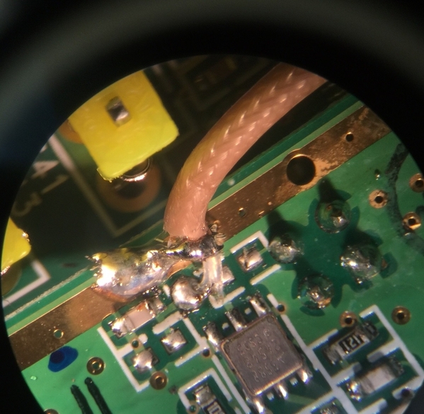
You need to find a nice omni-directional 868/900 MHz antenna like this one. Then just drill a hole in the TIU to feed the cable through, and solder it to the radio board to the same place the existing antenna goes. The ceiling isn't really necessary, just having the antenna on the surface of the layout is good enough to get you a few 100 ft range.

Add Reply

Post
The DCS Forum is sponsored by

OGR Publishing, Inc., 1310 Eastside Centre Ct, Suite 6, Mountain Home, AR 72653
800-980-OGRR (6477)
www.ogaugerr.com

×
×
×
×
Link copied to your clipboard.
×
×