Hi GRJ ,
can you tell me what oscilloscope you used for your tests
Thanks Fred B


|
|
Hi GRJ ,
can you tell me what oscilloscope you used for your tests
Thanks Fred B
I use the ATTEN ADS1102CAL, but any 'scope with 20mhz or more bandwidth would be sufficient to do the testing. Not much I do on the bench taxes the 100mhz bandwidth of mine. You can probably pick up a decent 'scope for not much money if all you are interested in is using it around model train electronics. Here's a decent one that's similar to mine, $245 shipped.
Hantek DSO5102P USB Digital Storage Oscilloscope 2 Channels 100MHz 1GSa/s
eBay: 223444992742
Thank you GRJ I’ll check them out
Fred B
I ordered 2 kits from Tom a while ago and finally got around to assembling one. Other than the pads on U1being really close, soldering was straight forward.
I powered it up and all seemed to operate fine. I started Stan's calibration and verified 5 volts. I set the pot in the middle and momentarily touched I had a red light flash. I rotated the pot to both extremes and got the expected results of neither flash and both flash.
The problem - while making adjustments, I apparently had my probe slip from one side of R11 to D2 while I connected to D1. Now when I power up with no DCS signal the red light comes on and stays on. The power LED comes on and there is still 5 vdc. Figured I blew one or more components.
Does anyone have a thought on which one or other simple measurements to isolate?
Ken
Well, the most likely would be the CD74HCT123E or one of the diodes I'd imagine.
Thanks John. The DIP is easy to replace since it is plug in. If D1 is bad and I swap out DIP, any chance it will cause new DIP to fail? D2 checks out ok when measuring in circuit. I guess I could unsolder one lead of D1 and check.
GRJ, the diodes are 200v 1A (1N4003, same as what you used), does that make the HCT chip more suspect? And there is a path directly to the HCT's Vcc when connecting D2 to R11 and D2 is track voltage.
Very Scary, I know, but this has gotten me to print out the schematic and look around a little. Trying to gain better understanding here myself.
Ken, Didn't see your 2nd post above when I was posting earlier, I would wait for GRJ's reply to be safe here. Good luck and I hope you get things going again. Sorry, but I don't think I have any extra parts other than for the remaining kits I have, but if you need Digikey numbers let me know.
Connecting R11 to D2 would be very bad for the health of the IC, so replace that first. If D1 is bad, it won't cook anything, the unit just won't work. Since you have 5V, D2 and U1 are still OK. I'd say U2 and D1 are the top suspects.
Replacing CD74HCT123E did the trick. I just ordered a few replacements from digikey.
That makes the most sense, it's probably the most delicate part on there. ![]()
Glad you got it all going again and the CDHCT123E is not too expensive either. I looked around but didn't have any extras, they were all accounted for in the remaining kits I have left.
John or RTR- I finished assembling my board recently. I'm having a bit of trouble getting +5V out of U1. Appears I may have a short from U1 pin 3 to 2 somewhere. I did verify no solder betweeen the leads of U1 as pointed out they are close. I'll double check that and some other stuff.
My question is when powering up for calibration using the 'Stan procedure' should the power supply to the signal tester board be current limited if using only an external 18V AC power supply? or (and) is TIU necessary for calibration?
Thanks Mike
My guess would be the solder connections on U1 are touching somewhere. I had the same problem myself with one PCB I assembled and a couple of others have had that problem as well. I removed all the solder from U1 with some solder wick and started over with much better results the second time, as did the others I know of that were having the same problem.
As for the power and calibration, I also used Stan's method detailed in his video posted in the thread. I use alligator clips to connect the tester to track power (with nothing on the track) and did the calibration the same way, as memory serves. I use PH-180s for track power so no current limiting here and they go through my TIU to get to the track. As I recall from following along in the design process here, GRJ's final design drawings were meant to use track power to drive the TIU Tester so no external power source was needed.
For the definitive answers on calibration I would wait for GRJ or Stan's comments just to be sure (and safe). I am by no means even anywhere close to being as knowledgeable as either those guys, I'm still just a greenhorn.
I'd be looking at U1, it's a problem area. I've actually started to use a new footprint I created for TO-92 packages to spread the leads out a little, the library pattern is not very easy to deal with.
I'm glad you did that. I was going to try adjusting that myself, if I ever needed to order more PCBs for the testers. I have quite a few on hand so it will be a while if they ever sell out. Orders have dropped off the last few months.
I was just trying to make a different PCB the last couple of days (Diptrace) and the component libraries and patterns are a struggle and quite a bit over my head so far.
I just built mine and when I try to calibrate it the green LED lights but I get nothing from the red. Any idea what the problem might be? I checked all solder joints and component placement.
is the red LED reversed?
Can you put around 2+ (2.5?) volts DC directly to it and see if it lights? I use 2 AAAs.
Joe,
The flat side is too the left as per the instructions.
The red LED is bad or you have a wiring error. Anytime the green LED comes on, the red LED should already be on.
att rhr12 just sent you an email would like to purchase 2 tiu testers !
thanks Alan Mancus sent you an email!
stan2004 posted:Here's one minimalist approach to "calibration" - no scope, no battery, no other components required! This uses the relatively accurate on-board 5V voltage as a reference.
With the 2 LED method (vs. original 1 LED method), there are 3 "zones". (1) BOTH LEDs blink meaning good signal level, (2) 1 LED blinks meaning marginal/degraded signal, (3) Neither LED blinks meaning very low or no signal.
1. Apply AC track voltage to module. Presumably the "Power" LED turns on. Use DC voltmeter to confirm you have 5.0V DC at the point indicated. The DC- side of the DC measurement is the circuit ground.
2. By momentarily touching +5V to the DC+ point as shown (using, say, an alligator jumper cable), you are effectively applying a 5V trigger. By turning the trimpot fully in one direction, you should be able to make BOTH LEDs flash each time you tap +5V to the DC+ point. By turning the trimpot fully in the other direction, you should not be able to make either LED flash. The idea is to adjust the trimpot to the case where you're at the threshold between NEITHER LED flashing and 1 LED flashing. To be clear, this is a separate threshold than between 1 LED flashing and BOTH LEDs flashing.
This simple (?) procedure "calibrates" the unit to flash both LEDs on a 10V DCS signal. This is probably good enough IMO but to each his own.
3. If you have access to a "known good" TIU channel, it will surely trigger BOTH LEDs as it appears you get more than a 10V DCS signal. You can then further adjust the trimpot with the "known good" TIU knowing that you have AT LEAST a 10V output. To do this, you then send a real DCS signal out the TIU and adjust the trimpot to the point where 1 LED flashes and BOTH LEDs flash.
bump for calibration technique post
stan2004 posted:For those that don't have an oscilloscope, here's a video showing the calibration method I suggested earlier using the on-board 5V DC voltage as a reference level:
As it turns out, you can simply short the wire-leads from two adjacent components (D1 and R6). Or as engineer-joe suggested, you could attach a momentary SPST push-button switch to these points if the circuit is mounted in a box whereby you don't have access.
Note I added a drop of white paint to the trim-pot to better show the adjustment angle.
This sets the threshold to about 10V. You can then further refine/trim the threshold to a known-good TIU output. Note that turning the trim-pot CW increases the threshold. The idea is without a starting point (10V in this case), you don't know if your "known-good" TIU output is at the desired 12V (or whatever) signal level. As Adrian previously reported, you can get all 10's on the DCS signal test with a signal level of less than 5V; but a TIU port that only puts out 5V is probably damaged.
Again, thanks to rtr12 for putting together these kits!
Barry Broskowitz posted:Susan,
To properly use the tool:
Turn on speed Mode in the remote.
Do not have an engine on the track.
Connect the test tool to a TIU channel.
Put power to a track on the TIU’s channel.
Start up an engine in the Active Engine List (that isn’t on the tracks).
Send commands.
Monitor the tool’s responses.
some more points to follow
Truthfully Joe, the tool was originally designed to simply measure the open loop signal on the TIU channel with nothing attached. Any mention of "track" in the picture will negate any calibration as every layout is going to present a different load to the DCS signal frequencies.
Remember, this is a DCS-TIU Port Tester Tool.
gunrunnerjohn posted:Truthfully Joe, the tool was originally designed to simply measure the open loop signal on the TIU channel with nothing attached. Any mention of "track" in the picture will negate any calibration as every layout is going to present a different load to the DCS signal frequencies.
Remember, this is a DCS-TIU Port Tester Tool.
GRJ is right, the track loading will make the tool act funny. You "could" do this with an elaborate before and after scheme. Like if you connect the track, then calibrate, and just leave it there for all time.
Even a bulb will adversely affect the signal. You need to uses this to test the output of the TIU directly. Also remember this only test the Transmit side of the TIU. Does not test the receive side. Both required for Engine operation under DCS. G
Correct, but it seems the transmit side is the one that gets abused and loses signal strength most often.
To properly use the tool:
Turn on speed Mode in the remote.
Do not have track connected to outputs
Connect the test tool to a TIU channel output.
Put power to a TIU’s channel and TIU
Send commands.
Monitor the tool’s responses.
OK, then I could alter the list??
This is good information that I should probably work into the info I have been including with the TIU 'PORT' Tester kits. I'll start using the proper name (adding PORT) as well.
That would make them more accurate for the calibration, that's for sure.
If I want to check the actual track signal on the track, I do it with a 'scope and a hi-pass filter to knock out the 60hz power and leave the DCS signal.
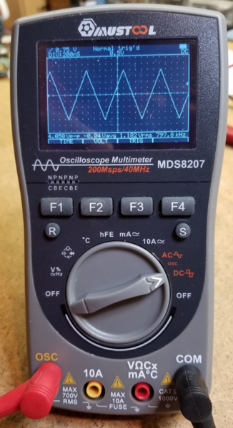
I use my MUSTOOL MDS8207 Intelligent Digital Storage Scopemeter and the simple filter to check actual DCS levels on the track. I can wander around a layout and measure at various points to see how the signal strength changes at different points.
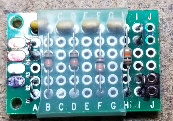
The filter board connects to the track on the left, and to the 'scope on the right. It's just four .01uf caps and four 10k resistors. Adrian was nice enough to post this, I just copied it. ![]()


I saved your post above for reference too, that's good info. I may even get this scope thing figured out one of these days...there sure are lots of push buttons, knobs and menus on this thing! I think I like yours better, only 6 push buttons and one knob! ![]()
I also saved the rest of the new info above to update the instructions and change to the proper name. Sometimes I'm a bit slow to notice the obvious, even when it's right in front of me. ![]()
I have to tell you Tom, it took a bit to learn all the in's and out's of the ScopeMeter. Even measuring voltage isn't as straight-forward as a regular multimeter.
gunrunnerjohn posted:Correct, but it seems the transmit side is the one that gets abused and loses signal strength most often.
So, I am in the repair business. I can't say the transmit side works great, sorry it still doesn't work for your layout.![]() The fact is, I get a tiu not working I have to run the transmit test first. If that is all good, or not and repaired, I then have to run a end to end test on receiver using a PS-2 board. Interesting enough I have found bad receiver can adversely effect Transmit strength too.
The fact is, I get a tiu not working I have to run the transmit test first. If that is all good, or not and repaired, I then have to run a end to end test on receiver using a PS-2 board. Interesting enough I have found bad receiver can adversely effect Transmit strength too.
The tool is a great help, but not the end all for validating TIU operation. G
GGG posted:The tool is a great help, but not the end all for validating TIU operation. G
On that point you'll get no argument from me! Clearly, it's just one tool in the toolbox.
gunrunnerjohn posted:I have to tell you Tom, it took a bit to learn all the in's and out's of the ScopeMeter. Even measuring voltage isn't as straight-forward as a regular multimeter.
Ok, I feel a little better now that it's still somewhat difficult even with fewer push buttons and knobs. ![]()
Once I get all the knobs, push buttons and menus figured out, I have to learn what all the fuzzy little lines on the screen are telling me. ![]()
I am still enjoying it though, it'll be great when/if I get this stuff all figured out. ![]()
The fuzzy lines are telling you that you need to do more studying! ![]()
![]()
GGG posted:gunrunnerjohn posted:Correct, but it seems the transmit side is the one that gets abused and loses signal strength most often.
So, I am in the repair business. I can't say the transmit side works great, sorry it still doesn't work for your layout.
The fact is, I get a tiu not working I have to run the transmit test first. If that is all good, or not and repaired, I then have to run a end to end test on receiver using a PS-2 board. Interesting enough I have found bad receiver can adversely effect Transmit strength too.
The tool is a great help, but not the end all for validating TIU operation. G
G
Above you mention testing the TIU receiver portion with a PS2 board, can you describe this test procedure? At the club, we are currently running 8 TIUs and every so often I check the TIU transmit side with a scope or the TIU port tester tool. At the same time, I would also like to test the receiver side to see if there are any issues with the TIU.
Thanks,
Bob D
NJ HI Railers
gunrunnerjohn posted:The fuzzy lines are telling you that you need to do more studying!
Advice always welcome here, I need all the help I can get! ![]() Back to the fuzzy lines...
Back to the fuzzy lines...
The TIU transmitting a signal to the engine is the first part. The engine then responds and that signal must be received by the TIU. I just use a known good PS-2 board and my test fixture. Make sure the engine adds, and that I can get a 10 signal back on a DCS Signal strength test. Remember that test is not only out going, but TIU properly receiving the return signal. The receive chip has 4 channels and can go out in signal, pairs or all 4 channels. Interesting enough I have also found that when degraded, it can actually effect the out going transmit strength. May be a heavy load on the 5V power supply, with the lower voltage effecting the transmit output, or maybe something else. Any way, the only way I can validate full operation is with a end to end test. G
Access to this requires an OGR Forum Supporting Membership


