
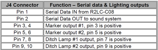
Does anyone happen to have a locomotive wiring schematic for the above Lionel loco? I'm doing a ERR Cruise "M" upgrade and have run into issues with a high resistance short to ground. When I pull pin 8 from the ERR Cruise "M" connector "J4", the short goes away. The short manifested itself by blowing the C/B on my Powerhouse after about three seconds of being powered up.

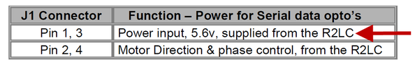
The wire from pin 8 goes to a heat shrink-wrapped PC board that appears to likely be a DC regulator board according to the parts breakdown on Lionel's site. From the ERR Cruise "M" instructions, this regulator feeds outputs for ditch lights and also goes to pin 1 of the "M" board connector "J1" which is noted to be a power input of 5.6V "supplied from the R2LC".

For history purposes, I started the Cruise "M" install on this loco after pulling it off the display shelf and noting that it did the "Odyssey stutter" about six inches and then refused to move further in either direction. With this regulator board now out of the J4 connector, the locomotive will not run in either direction.

Any ideas appreciated.....

Larry

Original Post

Replies sorted oldest to newest

Ditch lights?  Are you talking about ground lights?

You should start with ONLY pin 1 in the 10-pin CC-M connector, don't connect the other stuff.  Verify what those other pins are connected to as the CC-M doesn't have the same functions.  The CC-M outputs ONLY drive an LED, nothing more.

Connecting something to J4 and tripping breakers sounds like a recipe for disaster for the CC-M!

Attachments

Images (1)
  • mceclip0
Last edited by gunrunnerjohn

Hi John: I'm glad you chimed in here; Your second sentence SHOULD be in Scott's ERR Cruise "M" instructions. I DID remove pin 10 from the locomotive's J4 connector, but then plugged it in directly to the CC"M" board. Scott does supply the new J4 connector with only pin 1 inserted, but does not say "why" THAT connector should be used in place of the one already in the locomotive.

I did verify the other wires already in the locomotive and they were two ground wires + three wires going to the "flickering" firebox LED board. Pin 1 is soldered to the R2LC MB pin as directed for serial data. Two more wires were power for the locomotive's 2 LED marker lamps.

The short circuit was somewhat unusual in that noting got hot or smoked - it just popped the breaker. I'm not at home to work this, but tomorrow I'll just wire the serial data wire up and see what happens. When it did power up before with the J4 connector removed, I got locomotive "at rest" sounds + any keystroke on the Cab2 was met with a whistle from the tender.

I may have smoked this board, if so, time to eat crow. I've done almost a dozen CC installs with no issues. It just proves the CC"M" install instructions need more clarity in some areas and the purchasers should know  this is just not the "plug and play' install the advertisements seem to portray. One other area of concern I noted was the pin lengths on the bottom of the CC"M" board need to be trimmed before installing in the heat sink you remove-they would short on mine if left unattended to prior to installation.

I'll keep you posted on what I find out.....


D&H 65 posted:

Hi John: I'm glad you chimed in here; Your second sentence SHOULD be in Scott's ERR Cruise "M" instructions. I DID remove pin 10 from the locomotive's J4 connector, but then plugged it in directly to the CC"M" board. Scott does supply the new J4 connector with only pin 1 inserted, but does not say "why" THAT connector should be used in place of the one already in the locomotive.

I did verify the other wires already in the locomotive and they were two ground wires + three wires going to the "flickering" firebox LED board. Pin 1 is soldered to the R2LC MB pin as directed for serial data. Two more wires were power for the locomotive's 2 LED marker lamps.

The short circuit was somewhat unusual in that noting got hot or smoked - it just popped the breaker. I'm not at home to work this, but tomorrow I'll just wire the serial data wire up and see what happens. When it did power up before with the J4 connector removed, I got locomotive "at rest" sounds + any keystroke on the Cab2 was met with a whistle from the tender.

I may have smoked this board, if so, time to eat crow. I've done almost a dozen CC installs with no issues. It just proves the CC"M" install instructions need more clarity in some areas and the purchasers should know  this is just not the "plug and play' install the advertisements seem to portray. One other area of concern I noted was the pin lengths on the bottom of the CC"M" board need to be trimmed before installing in the heat sink you remove-they would short on mine if left unattended to prior to installation.

I'll keep you posted on what I find out.....


I have run into that many of times.I once got a video camera that had instructions.But only in chinese  which really made me angry.And yes instuctions can leave out a lot of things.

I am not sure what you have going on, but the big WARNING when replacing an ODY motor driver with Cruise M is that ODY has Chassis ground which is AC.  CCM is DC reference Ground.  Hence the warning in the instruction to cut the Chassis Ground wire in the ODY Swap on the 10 pin.  If the ground wire (pin8) you left in was going to a 5V Regulator on chassis ground, you blew the CCM board.

I don't know what is going on with Lionel's service manual website, but it seems like wiring diagrams that use to be accessible are no longer accessible.  Can't even pull up instructions for engines.

Frankly when adding CCM only pin 1 and 2 for serial in and serial out as buffered for some systems should be used.  IF your going to go back and add ditch lights in, you need to be sure you trace how they are wired.  Following the ERR Instructions for the Diesel mod for ODY and understand how it impact a steam upgrade.  G

Long ago I downloaded all the Lionel supplements so I'd have them locally.  However, I didn't find the wiring diagram for this particular unit.

George, what do you use pin 2 on the CC-M for?  I've never found a use for it, and when I did connect it to the RS Commander, I didn't get command control of the sounds.  I figured if it was buffered, that would be a solution instead of a transistor buffer, but it was no-go.  I can honestly say in 100+ installations, I've never used that serial output.

I've always meant to 'scope the two pins to see what actually comes out of that pin, and how it differs from the serial input.  It's just never risen to the top of the queue.

George & John: I just tried my loco with just the serial data wire on pin 1 of connector J4 and it was a no-go; no surprise there. Nothing like smoking a c-note to make your day....

Anyway, I have a question about the 5V regulator that came with the engine originally; my impression from your information George, is that there should be NO input from the 5V regulator board to the CC"M" board, however, my 5V regulator board had a yellow wire output going to the DCDR (and now) the CC"M" board's J1 connector pin 1. Why is that needed if the CC"M" instructions state that that pin should be "Power input, 5.6v supplied from the R2LC". I had that pin removed for my latest test this morning; do I still need that input? - seems counter-intuitive to me.....

I have another CC"M" board I can use to swap this one out, but until these issues are "plain and simple" as far as initial wiring, I'm holding off further adventures in electronics. Appreciate your inputs.

John, We had this discussion long ago.  I rarely see it either, but there are some installations that do use it.  I do not fully remember what Jon Z said about it, but probably some method of the ODY board feeding info to the sound system.

D&H For some installations I guess Lionel did not feel that the R2LC reg was up to snuff for the 5V loads and they supplied a separate regulator to power the DCDS.  I have seen engines with it.  It is ok for it to power the CCM, but not connect any of it to the 10 pin connector.  Basically it takes track power in and makes 5VDC.  Sometimes driving other lights too.  If they got DC ground from the original 10 pin for ODY, vice a chassis point, that may have caused issues with your CCM if left in the 10 pin.  G


J1 gets the four pin connection from the motherboard with the PWM signals and the 5V from the R2LC.  It's a plug-n-play affair, just move the connector to the CC-M from the DCDS.  You should not be doing ANYTHING but moving this connector to the new board.  Don't use their regulator, it's not needed. 

The CC-M will work with the J1 connector, the J3 connector, and pin 1 of the J4 connector.  I've never felt the need to connect a cruse enable switch, so I never connect anything to the programming connector.

The marker and ditch outputs on J4 are for a single LED, and as I stated previously, I've never used the J4 pin-2 output.

I think the reason that they used the regulator for the DCDS is they were also using the R2LC 5V for the IR tether transmitter.  Since the regulator on the R2LC is just a TO92 package, it's only good for around 30-35ma, and driving the opto-isolators on the DCDS and the IR drawbar must have been too much.

Last edited by gunrunnerjohn

In the pictures, this was stock configuration. J7 on motherboard has pin 1 empty. I added a jumper from pin 1 on J7 to pin 1 J1 on Cruise M which aligns with the harness that is included with the kit. Pin 3 on J7 goes to the IR. Pin 3 on J1 which used to fee the DC board is not used. Pin 10 on J4 on cruise is unhooked and I removed it from J8 on the motherboard too. Mine would not function correctly if I just did a plug and play with the J1. When I used the supplied J1 it went to working properly. When I plugged pin 3 back in to the DC board it would stop running after a while. I unplugged the DC board and it’s been fine since.

After looking at it, it looks like the DC board is not doing anything in that configuration. 

Attachments

Images (4)
  • 3F099FF8-E38A-4CD8-B918-63CECE7D8F59
  • A357FE99-8A6B-49D5-9B82-53537DB7C7B8
  • D8AA8867-83D5-4AAC-81D9-56C80E16CFE7
  • 384616CA-3F9D-46CD-819D-004122BA3E89
Last edited by SPFord27

I'd get a 4-pin to 4-pin connector from the motherboard to the CC-M, do the required splices to add the 4-pin black Molex connector for track power and motor drive, and run pin 1 of J4 to the serial data.  Get that working first before you look into adding any lighting, etc. driven by the CC-M.

Truthfully, I simply replace the 6-pin black Molex power connector with the correct 4-pin one, I hate splices where they don't have to be.

Gentlemen: The saga continues this morning on my Mohawk Cruise "M" install. I swapped in a new Cruise "M" board using the advice in this Post. I have seen no issues with shorts this time; I set Feature code "4" for steam with smoke. The engine Railsounds works normally and I can fire the tender coupler and reverse direction (as noted by the tender backing-light. I still have no motor response in either direction.

From reading the Cruise"M" instructions, it appears to me that I'm not getting the correct serial data needed to make this engine operate. I have attached a picture in the area of the Cruise"M" J1 connection to the Motherboard J7 connection; does this look correct? I should note that as the engine was built by Lionel, there was yellow 5VDC wire in the hole above the green wire in the picture the Cruise "M" J1 connector, pin #1.

Otherwise, the blue wire in Cruise"M" J4, pin 1 is soldered directly to the R2LC's pin 24IMG_2175

The green wire and black wire pictured just loop from one connection to the other. The wire in the upper J7 pin with red tracer goes to the IR tether.

Attachments

Images (1)
  • IMG_2175

Actually, with no serial data, the symptom is normally it takes off at full speed as soon as you crack the throttle.  Check the 4-pin connector from the motherboard to the CC-M.

I only see two wires in the PWM connector, so you have no 5V to activate the opto-isolators, that's your problem.  This connector should have four wires 1:1 from the motherboard to the CC-M, I think that will fix the problem.

You have no power to the input optos.

Attachments

Images (2)
  • mceclip0
  • mceclip1
gunrunnerjohn posted:

Actually, with no serial data, the symptom is normally it takes off at full speed as soon as you crack the throttle.  Check the 4-pin connector from the motherboard to the CC-M.

I only see two wires in the PWM connector, so you have no 5V to activate the opto-isolators, that's your problem.  This connector should have four wires 1:1 from the motherboard to the CC-M, I think that will fix the problem.

You have no power to the input optos.


The harness with the new cruise m comes with a 3 wire set up for J1. 1, 2, and 4. 

Last edited by SPFord27

Curiosity got the best of me. I snatched the shell off mine for another issue and while I was in there I unhooked the 5v source from the motherboard and used the DC regulator. Wow! This thing is fast! The DC regular seems to be useless with this configuration. It sounds and looks like your set up electronic wise is very close. I went on and just removed the regulator from the engine. 

John: I think I'm getting closer to fixing this thing; from what I understand from your last post I need to get a 5VDC supply to the C"M" J1 connector. The second photo shows a four pin harness that came with the kit. Should that be used instead of the Lionel original wire harness to get the direction and phase control inputs over to the C"M"? If so, my Lionel J7 connector has one side of the IR tether wiring in the slot inboard of the green wire in my previous picture-either end of the new harness takes the place of that wire, so what is the correct placement of the IR tether wire?

This first photo is just to show the blue wire feeding J1 on the C"M" board along with a 5VDC wire feeding the IR "buffer" 3rd Rail supplied.

I guess I need to know whether the needed 5VDC will come over to the C"M" J1 connector via 3rd Rail's supplied harness pictured? If that's the case, where should the line from the IR tether be installed?

Thank you all for your direction!

IMG_2176IMG_2177

Attachments

Images (2)
  • IMG_2176
  • IMG_2177

You should have been able to use pin 1 on the 10 pin like it was and pull pin 10 on the 10 pin. On the 4 pin, leave the IR wire where it is on the motherboard and put a jumper in pin 3 from the cruise m to the motherboard. You can use the harness as err sent and move the IR wire to pin 3 on the motherboard too. Either way, you need a wire in either 1 and 1 from the motherboard to the cruise m or in 3 and 3 in addition to 2 and 4. You will end up with 3 wires from the cruise m to the motherboard. Put the IR in pin 1 or 3. 

For the time being, just use the harness that came with it. You will lose your IR until you plug it back into the open hole on the included harness.

Last edited by SPFord27

John: OK, I'll give that a shot; it still begs the question where the one IR tether wire presently in Lionel's J7 pin1(?) on the motherboard will go once the 3rd Rail harness is swapped in......

And again, NO WHERE in the Cruise "M" instructions does it logically say to use the new harness-they reference using for K-Line locos and that the Lionel harness "will have this same connector attached to the board you remove, and this connection will directly connect to the Cruise "M"."

Sorry I'm being careful as burning one C-note is enough for my budget.....

Well, you can either use the separate 5V supply that was there or connect it to the one open terminal on the CC-M that has 5V on it.  I can't honestly say if the CC-M and the IR tether will be too much load for the 5V supply, I'm guessing it'll probably be OK.  I know many are running in that configuration.

The instructions obviously didn't anticipate the separate power supply, that's all I can think.

There are so many minor variations in the wiring of these things that sometimes you have to do a "seat of the pants" change in the wiring.

Good day John: Progress has finally reared its ugly head on this project; my 2793 now runs/smokes and talks again, actually it runs MUCH better than stock. I plugged the remaining IR tether wire into pin 3 on the J1 harness 3rd Rail supplied and it seems to like that.

My final question concerns the headlight; it appears to be a grain of wheat bulb; do you know what voltage Lionel would typically use in this application? My gut tells me it will have a very short life connected direct to track power.... That 5VDC regulator may come in handy after all.

Thanks for all your technical support!

Larry

Hi John: I have the loco all buttoned up with lights/smoke/Railsounds all working and the locomotive has awesome speed control the Lionel unit did not have. The only deletion I did was the flickering firebox-I could add that later but it wasn't a big priority.

My one question I have left concerns programming the Cruise"M"; per the manual I set feature code as "4" which is steam with smoke. I checked settings in my CabII for the engine and have it set for "steam/TMCC/Railsounds". I only ask if that is the preferred set-up as the top-end on my engine is reduced from "normal" by quite a bit, i.e. my CabII speed bar can be showing "28" and the engine is running more like a "10". Does ERR prefer operating as a "CabI" controller?

Remember, the CC-M has 100 speed steps, not 32.  It's running fine, you just have finer speed control!   If you have the type in the CAB1 set for TMCC, change it to R100 and you'll get the correct graph and all will be well.  You have not lost any top-end speed, you can still go fast enough to leave the tracks.

Last edited by gunrunnerjohn

Add Reply

Post

OGR Publishing, Inc., 1310 Eastside Centre Ct, Suite 6, Mountain Home, AR 72653
800-980-OGRR (6477)
www.ogaugerr.com

×
×
×
×
Link copied to your clipboard.
×
×