The scenery looks great! Your helped did a fine job!!
You and your helper have done nice work! Does the helper approve of the result? If, yes , then , it is good to go.
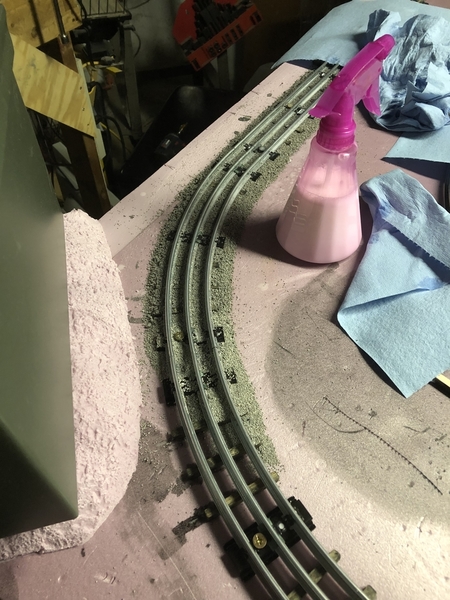
Why don't you brush the ballast a little thinner on the inside rails? You made the extra effort to add the ties and now they lost under the ballast.
Even though outside activities prevail, it is good to take some time and still touch something on the layout.
Thanks for update!
looks great you guys !!!
Well... 5 months pass... and its getting toward time to get back to the layout..
Some things have changed in our lives - mainly - we now plan to stay in our house for at least 5 more years (Previously we had planned to move in 2 or less)....
So now I'm back to thinking about the basement as a whole - and what a general mess it is.
Bottom line - I may be doubling (tripling?) the amount of space I have and going to 10X18 or even more with extensions into the other are of the basement (semi around-the room is possible).
My wife is open to the idea - so depending on my motivation level - I may be ripping *everything* out including existing shelves and tools..
I'm glad I did this layout as it is, because I've learned a TON in the process.. but it has also shown me a lot of areas where I made mistakes.. access for example - there are places you just can't reach if the train derails.. and the switching issues I mentioned earlier - the trains really are struggling.. making me consider going with either Atlas or GarGraves and better switches... plus increasing to a minimum of 54" or 63" diameter turns..
Ive attached an idea for a starting point... but really have no idea how I want to do this..
Attachments
IMHO, I would do away with the isthmus/peninsula connection and leave it closed as a simple yard area. The way you have it now creates two inaccessible areas . By having it close ended, you open up the area inside to walk around and the track connection you show doesn't really do much.
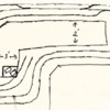
In addition, depending on how wide the peninsula is you might be able to fit an O-27 closed loop at the bottom, even with it being closed off. See Fig 2.
Just my $0.02
Attachments
Richie C. posted:IMHO, I would do away with the isthmus/peninsula connection and leave it closed as a simple yard area. The way you have it now creates two inaccessible areas . By having it close ended, you open up the area inside to walk around and the track connection you show doesn't really do much.
In addition, depending on how wide the peninsula is you might be able to fit an O-27 closed loop at the bottom, even with it being closed off. See Fig 2.
Just my $0.02
I like that idea - and had something very similar sketched!
I added the loop as a reversing loop.... but I may be able to fit that in as well elsewhere... I'm going to properly measure the other half of the basement - and maybe if I get creative I can wrap around a good portion of the furnace and throw a reversing loop over there.. Just need to have access from one side.
Progress on the basement cleaning and garage cleaning continues... Looks like this is definitely going to happen now - I've made enough room to clear the area out..
Plyaing around in CAD here at work and came up with this... using standard GarGraves 72,63 and 54 curves.. Three mainlines with some yard areas. I'm thinking of having a "town" or industry in each corner.. and then the main yard in the middle.
Attachments
I'm thinking the outermost mainline will be elevated (hills / mountain) on the left side of the layout and transition back to lower level on the right - then some tunnels at the bottom left for the front two loops - this will allow access from the back .
Probably going to pull the elevated loop further away from the other two to allow for the elevation changes.. also going to play with switch positions, etc... I have to look at a bunch of back issues of OGR to find examples I want to emulate.
Goal is to have tear out done and bench work laid by December so I can start playing with track and experimenting...
Escher posted:Playing around in CAD here at work and came up with this... using standard GarGraves 72,63 and 54 curves.. Three mainlines with some yard areas. I'm thinking of having a "town" or industry in each corner.. and then the main yard in the middle.
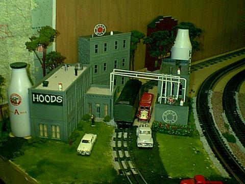
Foam board scratch built transfer buildings.
DPM kits and modules.
Two corners of our layout. John in Lansing, ILL
Attachments
Ohhh My Goodness... I cleaned and cleaned and cleaned tonight... But now the area is opened up and I can start tearing out the existing track - and then i will be ready to go.
Not sure if I mentioned it before - but in 2018 we had a drunk driver crash through our house - and in the ensuing madness - we dumped nearly the entire contents of the house into the basement and garage before it was condemned for repairs. It was a mess even before that - but that made it so much worse... So - this has been a monumental task. I'll snap some pics once I have the existing track and make-shift benchwork out.
Escher posted:
Hi Escher,
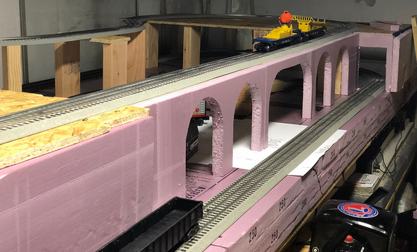
I went through your layout thread but not carefully. In the second and third picture of the bridge, may I ask how you created your arches? My first thought would be you used pre-fabricated tunnel portals as templates but I wanted to still ask just in case I am incorrect.
Thanks,
Dave
Hi Dave - arches are simply cut from 1” thick insulating foam with a hot wire tool. I chose a radius that looked nice (one of my wife’s saucers I believe!) and drew them evenly spaced for the desired span.. The middle large arch just has a straight section at the top.
Very handsome job!
Question for the group..
Since I'm starting over - I'm considering which brand of track to use. GarGraves seems quite expensive - but it also looks to be the type to go with... is there any other type I should be looking at? I'm moving away from traditional tubular and selling my existing o22 switches to recoup some of the cost..
Izak is right! Onward and upward!
Escher posted:Question for the group..
Since I'm starting over - I'm considering which brand of track to use. GarGraves seems quite expensive - but it also looks to be the type to go with... is there any other type I should be looking at? I'm moving away from traditional tubular and selling my existing o22 switches to recoup some of the cost..
Just a clarification... I may still use tubular track... I’m still flip flopping a bit in that regard as the price is right.. likely I’ll run tubular to start as I’m nailing down a track plan... and then I’ll decide..
I like the GarGraves stuff but it’s quite expensive for us...
My two cents as a tubular guy:
Gargraves definitely looks better, however, no matter what, we still have that pesky third rail. So while we are already suspending our disbelief and overlooking the middle rail, I don’t find it too much of a stretch to overlook the shape of the rail and tie size/spacing. When you added ties and ballasted the tubular, it looked pretty good too. If buying Gargraves and potentially Ross switches will slow your progress (buying in phases as funds allow), I’d stay with tubular. If money is less of a concern, buy the Gargraves and Ross all now and build it all at once. Bottom line, get it up and running while the young lad is engaged.
Made the decision this morning while surfing the local Menards stock online - I ordered some O54 and O42 curves and will be going with a dual mainline in tubular for the foreseeable future... I'll experiment with my exisitng O22 switches and see if I can space them out a bit more to avoid derailments (Switch to switch transitions were where most of my issues happened).
But - you are correct - I can get a lot of the same "look" with the added ties, and the tubular doesn't bother me.. I was "pie in the sky" with the GarGraves - until I started really digging into the prices.. Champagne taste on a beer budget as they say.
Regardless - Sunday will be a big day - going to go all out on trying to get the bulk of the benchwork in and a couple of functioning loops... a pretty tall order - but we shall see.
I apologize for all the flip flopping back and forth. I do that a lot - especially in thi shobby - as I'm running trackplans in every type of track (Fastrack, GarGraves, and Tubular). But I realize have to live in reality with regard to a budget.
Just upping my curve radii in tubular is going to be a huge improvement and allow me to run larger trains, while still not breaking the bank.... and I can keep the total cost of the project way down. I'm reusing a lot of the previous studs and screws... so all-in, I believe I will be under $400 for the project even with the new track..
First run today! Izak at the controls..
Great progress in a short time! Trains are running smoothly.
I saw your handsaw in one of the pictures above. It Reminded me of doing projects with my grandpa. He would always show me the “hard way” first, handsaw, manual drill, etc before breaking out the power tools.
Nice milestone! The Engineer is certainly pleased!
Excellent!
Took the advice from earlier in the thread about getting trains running as soon as possible... I wired all the power blocks (except the small yard I added as block 4) and did a test run last night with manual switching.... everything runs smoooth.
Tonight - final tweaks and maybe increasing some clearances to the walls - then I will tack the track down and start working on switch wiring.
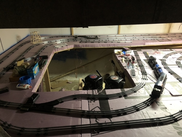
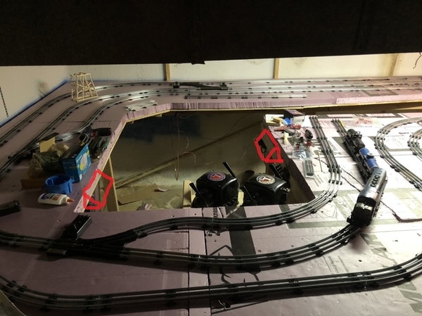
Question - Our control area is in the middle of the large cutout - center of the picture above.. I have both ZW's in there and its a bit snug, but very useable. However - I have no idea where to put my layout diagram and switches!!?? DOH! I can't do a board like I had previously unless I put it up high... I can squeeze the boxes in easiest if I space them out around the layout - closer to the actual switch machines..
Do you folks with larger layouts put all your switches right next to the throttles, or do you put them closer to the actual switch machine?
Not really sure what standard practice is.... I'm not opposed to walking to the other end of the layout when I want to switch mainlines... and that would save me a lot of pain in extending my switch wires - I'd only need to run a power and ground line.
Maybe you can separate the transformers and switches so one manages the yard, while the other manages the main lines. For switching, I think you will want transformer and switch control right next to the yard area. The outer mainlines, you can set the speed on the transformer and walk around to the switches or keep them near the mainline, either way it is easily altered if you want to make a change later. Something like this:
Attachments
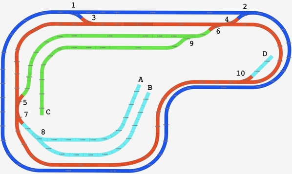
Apologies - I hadn’t posted an updated layout drawing.. here is a quick sketch... things had to be shifted around when the true space was realized as not quite as large as I hoped.. I also dropped a loop due to space and now have two mains and a passing siding.

... the “yard” is really just two stubs where I can build up trains while the mains are running..
Edit - Update drawing - didn't show the main loops interchange switches.
Attachments
I'm thinking that I may just put the mainline switches on the side opposite where my ZW's are currently... and keep the small yard switches by the control area - as you recommend.. then I just have to turn around to switch which loop I want.

This is where I would put the power and control - on this out side edge - One can see the entire layout fromthis point of view without turning or rubber necking.
Leave the inside for access when needed or make removable scenery in there
The direction that the transformers are facing in the post above has the engineer looking away from the layout.
Anyway, just my preferences - do what you like
Good point... In my exuberance for the new access areas inside I hadn't thought about putting things "outside"... Not sure if that specific location will work as its right at the foot of the stairs - and in the path... but, possibly where I had the control before in the bend of the L... provided I left enough room to still use the lathe.
Thanks for the suggestion!
Escher posted:Good point... In my exuberance for the new access areas inside I hadn't thought about putting things "outside"... Not sure if that specific location will work as its right at the foot of the stairs - and in the path... but, possibly where I had the control before in the bend of the L... provided I left enough room to still use the lathe.
Thanks for the suggestion!
Okay, I didn't realize there were outside constraints - I don't like the center of the outside or, in your case, the elbow of the L for the same reason. If you watch one area of the layout you are not able to watch the other. I run multiple trains simultaneously - it keeps me alert.
Wouldn't the corner move you away from the stairs? How much traffic will you have when operating? The control table can be on wheels and slide under when not in use.
Keep it mind for the future - you have a full plate now and are making good progress!
Escher posted:I'm thinking that I may just put the mainline switches on the side opposite where my ZW's are currently... and keep the small yard switches by the control area - as you recommend.. then I just have to turn around to switch which loop I want.
I would make two small panels with triangle block ends out a 2 x 4 and a surface of 3/16" board Mount to side of layout
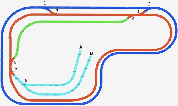
The red lines indicate isolation points to kill power to the track. Each K zone is one toggle switch.
Connect the cross-over switches together - Put SW 1, SW2, SW3 & K1 on panel facing that area
Put SW 4, SW5 and K2 & K3 on the panel to left
Make the panels as small as they can be to hold everything - use a number labeling system and place RR signs on layout to identify the switch or track section
Will that work? It is only a slight rotation in the chair to make it work.
Attachments
Escher posted:
Using one controller each for the crossover switch pairs saves space on the control panel and makes operation easier.
I would still suggest that A & B get isolated and get their own kill switch. Good place to park extra locos.
I missed the second red switch going to the light blue line.
You have to be careful with the voltage of Blue and Red when crossing over having those as two power divisions. If they are not close to the same voltage, they will bridge the two transformer channels.
Yep - A and B are going to have independent toggle switches so I can park loco's there...
I'm using tinman3rail dual switch boxes so I activate two switches at a time - going to pair up each set of two to change from mainline 1 to mainline 2...


