


I've gotten a few pieces of mail over the years that had a tough trip, it happens. I've gotten UPS and FedEx boxes that were crushed, wet, etc., all the shipping services have issues sending stuff I suspect. ![]()
gunrunnerjohn posted:


Got my 3 PCBs of this version from OSHPark yesterday and populated them today following GRJ's directions above. Quite tiny I might add, I used the Banggood microscope. It works as intended, just as Stan described in his earlier sample. These are very nifty little tools to have around! I'd like to try making one of Stan's truck mounted surge detector devices one of these days, as in his video above.
Also, I am now almost certain that I was not put on this Earth to work with SMT components! And these are the larger 1206 size (do they come any larger?). ![]() They even put tiny little orientation lines on the diodes, which I did not see until it was too late...good thing I had 3 PCBs and extra parts.
They even put tiny little orientation lines on the diodes, which I did not see until it was too late...good thing I had 3 PCBs and extra parts. ![]() I think my grandson is in need of some more soldering lessons!
I think my grandson is in need of some more soldering lessons!
Gee Tom, you just take the diodes off and turn them around! ![]()
![]()
After I realized my mistake, it was an extremely rare moment of frustration. So I moved on to another PCB with the intent of correcting the diode error and salvaging the PCB later. The challenge was to just get one PCB completed with the SMT parts properly attached. Although it was a bit ugly (well maybe a little more than a bit), PCB 2 was completed and tested successfully! Still struggling, but one down and more to play with. As they say, practice makes perfect.
If I ever get into anything much smaller I'm going to hire one of those robots that does this stuff for a living. ![]()
Once you develop a technique, it's not that bad to put SMD parts on. You should be using smaller solder, I use .020" diameter solder for PCB work.
- Secure the PCB, I use my PanaVise, though there are many methods.
- Put a dot of solder on one pin, since I'm right handed, that's a pin to the right of the component.
- Grab the part with the tweezers in your left hand, heat the soldered pin with your right hand, and slide the part into position.
- Remove the heat and let the solder solidify.
- At times, the part is sitting up and not firmly against the board. I just apply gentle pressure with the tweezers tip to the center and heat the solder again and let the part seat.
- Solder the other pin(s).
Rinse and repeat. ![]()
When you get to a more complex board, the order you mount parts starts being significant. Work from the inside out and do the short components first, then the higher ones.
That is pretty close to what I was doing with the exception of the vise. I'm using mounting putty or sometimes called blue tack, I think, but mine is white. Had it on the microscope base to hold the PCB. It works well at holding the PCB steady, doesn't move at all.
I did experience the part sitting up and not firmly against the PCB thing, Your tip helps here. I sorts did that, but it was a bit of a struggle as the component kept moving around when the solder heated up. I may have had too much solder on the first pad to start with? The 'technique' is still in the development stage! ![]()
I have the Hakko 888D and I was using a Hakko T18-B tip. It is pretty small, but maybe a smaller one would be better? It did seem kind of large compared to the parts. I have a few others and may have one that is slightly smaller, I'll check my stash. Which tip do you use in your Hakko for the SMT stuff?
I was using the 0.020 - 63/37 solder, and it's good quality from Digikey. It's not the cheaper Asian stuff. I have heard most of that stuff doesn't do so well on through-hole or SMT. Watched some youtube vids of folks trying it out, they weren't too happy with it.
Got a couple of emails from OSHPark today, more PCBs are coming. One is the through hole version of the TVS tester and the other is an earlier version of it in SMT form from before you shrunk it down. I'll have even more to practice with soon, probably by the weekend.
As for solder, I buy Kester solder, it's a recognized name brand and has always performed well for me.
I use the long needle point tip for most of my work with the Hakko. Here's a picture of the type of tip I use, this was just one I found on the Internet, but that's the type.

Attachments
Images (1)

I think I have a tip quite similar to that one, it's slightly different, but has a really small, sharp tip like that one.
Solder is Quick Chip or something close to that anyway. I have a Digikey order started, I'll see if they have any Kester and give it a try.
I did another one today and it was a little better, the technique seems to be improving slightly. ![]()
Chip Quick is very low temperature solder for removing stubborn parts, but it's very expensive to use as general solder! You get a couple ounces for $20, not exactly a bargain.
https://www.digikey.com/produc.../SMDIN100-ND/8681826
Look on Amazon, they have a good price on one pound rolls of Kester 63/37 Rosin Core solder. It's $23.99 for .031 and $24.95 for the .020, shipped free if you have Prime.
Was just on Digikey, Kester was $55.51 for 1lb of the 0.020. I'll check out Amazon for their Kester solder tomorrow. I really don't need a 1lb. spool. I forget exactly, but that might be how I ended up with the Chip Quick, it came in smaller sizes?
Hmmm...just took a quick look at Amazon, your prices were for a 1lb. spool, maybe I do need a that much. ![]()
That's why I selected Amazon. Digikey is great for parts, but for commodity stuff like solder, they're frequently quote a bit more expensive.
Slowly but surely, I'm learning! That is, with a lot of assistance. ![]()
I just wanted to report on a successful tester build using RTR12's DipTrace files, which he graciously made available. The boards are about $1.20 a piece from OSH Park. I built the thru-hole version using parts in my supply bins. Thanks to Tom; he did all the heavy lifting on this one!
Attached a couple of pix of the tester I just today assembled and tested. Works perfectly, as expected!
I had to drill the strain relief holes out to 9/64” to accept the test lead wires I had on hand. No big deal.
I am glad the board is no smaller than it is; it might get lost in the parts box otherwise! Haha.


Thanks Tom and the other contributors to this topic; and Stan for the original idea and circuit.
Rod
Attachments
Images (3)
Stan: I would love to hear your opinion on the O-gauge TVS mindset. Tell us what you think, if you would. I'm asking nicely.
Hi John
Can you post a direct link to OshPark for your TVS Tester so I can purchase some boards?
Thanks John!
Ordered. Makes things easier and its a fun project to assemble.
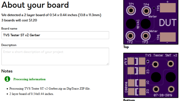
I took a look at this project again and did a minor Tweak of Tom's latest design ![]() I shrunk it so the boards are cheaper, and I also changed the contact point to test points for leads, I think I'd want to clip the TVS and then fire up the tester. Obviously, DUT is the Device Under Test. The Gerber files are attached below.
I shrunk it so the boards are cheaper, and I also changed the contact point to test points for leads, I think I'd want to clip the TVS and then fire up the tester. Obviously, DUT is the Device Under Test. The Gerber files are attached below.
A thought occurs to me when looking at this as well. In order to truly test a bi-polar device, you have to swap it's polarity and run the test twice to test it completely. ![]()


Attachments
Images (2)


Files (1)
I like that one! I made a later version, a bit larger with bigger pads for the TVS leads.. But I think I like the idea of clips for the TVS, no lead bending to try and hit the pads or having to hold them on the pads.
I may have to order some of those and give them a try with all clips. Or wait, I have some extras, I guess I could just solder some clips to the pads... Also, I hadn't thought of testing them both ways, that's a very good suggestion. Especially for us greenhorns (well me anyway)!
This is probably a good place to add a photo of a TVS installed in an MTH PS3 SW1500. The two gray wire nuts form junctions between incoming power from the roller-pickups (hot) and truck-frames (ground) and the power leads to the PS3 circuit board. Easy to stick a TVS right there:


I suspect this is SOP wiring in PS3 diesels in which case it's a simple solution for lots of people.
Attachments
Images (2)
I'd sure be insulating those bare leads! ![]()
Add Reply
Sign In To Reply
