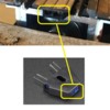
I had a turntable made. It is very hard to align by sight. 

I have learned that the Dallee indexer won’t work on it.  I have also learned that significant modifications are necessary to make a different system work.  

Does anyone have a suggestion?  Even some kind of physical markers to put up to help line it up by sight or some other index out there that works. 


In the absence of ideas, I have a beautiful 27” turntable available.  Lol. 

Original Post

Replies sorted oldest to newest

The gear drive or belt drive needs to be geared very low such as a Millhouse or Ross unit. I use a modern DC power pack from a train set to drive the unit. I can take the driver DC motor all the way down to a hum just barely moving the turntable for visual alignment. The only other solution would be looking at the indexer units offered from the two manufacturers stated above. Good luck.

Visual alignment accuracy can depend on where the TT is located.  Most of my TTs are close to the benchwork edge, rail alignment easily viewed. 

One distant TT is only  used to reverse an engine to the single entrance/exit track so I use a pair of stops on each bridge end to make a dedicated 180 degree turn

A small adjustment.  The inside ends of the bridge rail can be tapered with a small file or dremel.  Same applies to the fixed spur rails.  The small taper allows for slight miss alignments.  This Diamond Scale TT is aligned by sight.  Exit to main rails, there is a mark, on this side of the TT, used for alignment.  Older Diamond Scale TT kit.   Click on the triangle to access a Photobucket video. 

A DPDTX,  Double pole, double throw cross over switch with a variable resistor, DC motor drive. 


Diamond Scale drive. 

Modular Turntable build.   Fabrication, using Diamond Scale, Bowser, Kaplan Lumber and other scale parts. 


Last edited by Mike CT

Every real turntable I have been around i.e. WMSRR, EBT and several live steam/grand scale versions, all have a locking mechanism for turntable alignment.  

I do not have a turn table, however I have often thought that a solenoid or servo motor with a pin arrangement, that locked into a metal plate with a hole on the pit wall, centered under each track, would be a great way to line things up every time with a minimum amount of effort, if it was part of the original construction.  The device could be mounted between on the turntable bridge between the main structural members.  I am sure there would also be a way to make it less obvious than a series of holes in the pit walls, but that was my original idea.  One extra cable with two or three wires would be needed to activate it, you would only need to lock and align the side you are drive over.

jhz563 posted:

Every real turntable I have been around i.e. WMSRR, EBT and several live steam/grand scale versions, all have a locking mechanism for turntable alignment.  

Such "locking arrangements" are ONLY engaged AFTER the table is properly aligned to its respective track rails. Trying to engage any "locking arrangement" on a real turntable while still in motion results in a major disaster. 

I do not have a turn table, however I have often thought that a solenoid or servo motor with a pin arrangement, that locked into a metal plate with a hole on the pit wall, centered under each track, would be a great way to line things up every time with a minimum amount of effort, if it was part of the original construction.  The device could be mounted between on the turntable bridge between the main structural members.  I am sure there would also be a way to make it less obvious than a series of holes in the pit walls, but that was my original idea.  One extra cable with two or three wires would be needed to activate it, you would only need to lock and align the side you are drive over.

As stated in above posts, the best drive mechanism is the cog-belt system offered by both Milhouse River and Ross. We had a Bowser 32" turntable, up-graded with the cog-belt drive, and it was pretty easy to visually align the table to any/all of the tracks, i.e. just like real railroad turntables.


Hot Water posted:
jhz563 posted:

Every real turntable I have been around i.e. WMSRR, EBT and several live steam/grand scale versions, all have a locking mechanism for turntable alignment.  

Such "locking arrangements" are ONLY engaged AFTER the table is properly aligned to its respective track rails. Trying to engage any "locking arrangement" on a real turntable while still in motion results in a major disaster. 

I do not have a turn table, however I have often thought that a solenoid or servo motor with a pin arrangement, that locked into a metal plate with a hole on the pit wall, centered under each track, would be a great way to line things up every time with a minimum amount of effort, if it was part of the original construction.  The device could be mounted between on the turntable bridge between the main structural members.  I am sure there would also be a way to make it less obvious than a series of holes in the pit walls, but that was my original idea.  One extra cable with two or three wires would be needed to activate it, you would only need to lock and align the side you are drive over.

As stated in above posts, the best drive mechanism is the cog-belt system offered by both Milhouse River and Ross. We had a Bowser 32" turntable, up-graded with the cog-belt drive, and it was pretty easy to visually align the table to any/all of the tracks, i.e. just like real railroad turntables.


Would said anything about locking it while spinning?  The question is about final alignment.

You would still have to get close.  Then if you something like a 3/8" steel rod, tapered to a rounded 1/8" point, that engaged either a tapered hole or a slightly over 3/8" hole, the pin would do the final alignment.  Not suitable for Norfolk Southern, but a tapered pin that finalizes alignment works well in 15" gauge and 7 1/4" gauge live steam. Maybe I should have specified tapered pin to begin with, and I am sure the expensive drive system works well.  But for a repeatable system a physical connection is hard to beat.

Sound like you have a custom made turntable with no indexing system.  Does your turntable have a motor ?  If so, what does that install look like ?   Ross sells there indexing system as a kit.  The also have adaption to a Bowser turntable.   It's a cogged system which can index to any position.  It's probably the easiest to adapt.  You're most likely not going to find a drop-in indexer.

I have a Dallee indexer on my Bowser drive which is hooked up but I never installed the index sensor/alignment marks.  It always struct me as being too imprecise.  I have an on-off switch and reverse switch which allow me to make visual alignment.  Someday when I don't have anything to do and feeling rich, I'll go for the Ross unit.

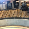
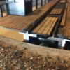
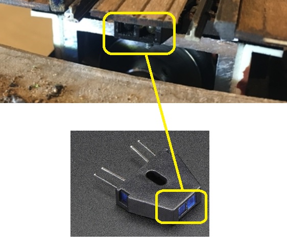
Not sure if this helps at all, I am in S scale. The TT was made by AAA and uses a simple IR transmitter/ receiver under the bridge track and a white alignment stripe on the pit wall under the center of each track. Should be simple to retrofit. The alignment requirements for the small S scale flanges are likely more critical than for O gauge high rail. The TT can be made to stop anywhere with a white stripe. These happen to be at 9 degree increments of rotation. The TT has functioned for two years without any adjustments or failures. Here is a picture of the alignment stripes and a picture of the IR head on the bridge.


47E89F94-FC5B-484F-9974-060CBB18341D057A356C-D63E-4AD0-BEF8-FBC4D29CCE5D

Attachments

Images (2)
  • 47E89F94-FC5B-484F-9974-060CBB18341D
  • 057A356C-D63E-4AD0-BEF8-FBC4D29CCE5D

Just brainstorming here:

How about a little indicator light circuit.  You could add a contact roller to the bridge, and as you turned the bridge, it would come into contact with a small metal pin head in the pit.  Each time you are perfectly aligned with the track, the contact roller would come into contact with the pin head and complete the circuit - light the lamp, and you would know to stop.  The light could be small LED on the bridge.

AmFlyer posted:

Not sure if this helps at all, I am in S scale. The TT was made by AAA and uses a simple IR transmitter/ receiver under the bridge track and a white alignment stripe on the pit wall under the center of each track. Should be simple to retrofit. The alignment requirements for the small S scale flanges are likely more critical than for O gauge high rail. The TT can be made to stop anywhere with a white stripe. These happen to be at 9 degree increments of rotation. The TT has functioned for two years without any adjustments or failures. Here is a picture of the alignment stripes and a picture of the IR head on the bridge.


47E89F94-FC5B-484F-9974-060CBB18341D057A356C-D63E-4AD0-BEF8-FBC4D29CCE5D

That is pretty great.  Does it stop at each white line, or can you turn on the IR transmitter/receiver when you are near to the desired track?

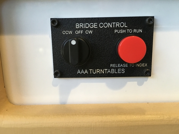
The TT is the only thing on my layout not operated with the Lionel LCS. Decided to just use this little control station at the TT area. The rotation direction switch is visible. Pushing the button starts rotation and holding it in causes it to rotate at the faster of the two speeds. When you want it to stop release the push button and it will slow dow to the low speed and stop at the next white stripe. I am very happy with how this works and use it frequently.


2598E67C-522F-4BE4-A36B-FBC698B0F45F

Attachments

Images (1)
  • 2598E67C-522F-4BE4-A36B-FBC698B0F45F

Lots of interesting thoughts here.  I like the idea of a led indicator, but it seems complicated in that you would need some kind of ring to supply power as wires would simply twist and pull out. 


I like the idea of filing the track to provide a little more margin for error.


I am looking for some physical mechanism that I could employ as my fabricating skills are a big zero. 

AmFlyer posted:

The TT is the only thing on my layout not operated with the Lionel LCS. Decided to just use this little control station at the TT area. The rotation direction switch is visible. Pushing the button starts rotation and holding it in causes it to rotate at the faster of the two speeds. When you want it to stop release the push button and it will slow dow to the low speed and stop at the next white stripe. I am very happy with how this works and use it frequently.


2598E67C-522F-4BE4-A36B-FBC698B0F45F

I love that.  Nice and clean. 

shorling posted:

Sound like you have a custom made turntable with no indexing system.  Does your turntable have a motor ?  If so, what does that install look like ?   Ross sells there indexing system as a kit.  The also have adaption to a Bowser turntable.   It's a cogged system which can index to any position.  It's probably the easiest to adapt.  You're most likely not going to find a drop-in indexer.

I have a Dallee indexer on my Bowser drive which is hooked up but I never installed the index sensor/alignment marks.  It always struct me as being too imprecise.  I have an on-off switch and reverse switch which allow me to make visual alignment.  Someday when I don't have anything to do and feeling rich, I'll go for the Ross unit.

I have a custom TT.  There is a 1/2 shaft driven by a motor.  No belt.  One of the frustrating things is that when you change directions, the motor has to spin a while before the shaft moves again.  So if you overshoot the target it is a hassle to get it to move back the other way.

davidbross posted:
shorling posted:

Sound like you have a custom made turntable with no indexing system.  Does your turntable have a motor ?  If so, what does that install look like ?   Ross sells there indexing system as a kit.  The also have adaption to a Bowser turntable.   It's a cogged system which can index to any position.  It's probably the easiest to adapt.  You're most likely not going to find a drop-in indexer.

I have a Dallee indexer on my Bowser drive which is hooked up but I never installed the index sensor/alignment marks.  It always struct me as being too imprecise.  I have an on-off switch and reverse switch which allow me to make visual alignment.  Someday when I don't have anything to do and feeling rich, I'll go for the Ross unit.

I have a custom TT.  There is a 1/2 shaft driven by a motor.  No belt. 

There lies most of your problem! I suggest you contact either Al at Millhouse River or Steve at Ross, and explain what you have. Either of them will be able to outfit you with one of their fool proof cog-belt & motor drive up-grade kits. Then you will be able very easily visually align your table bridge to any of your track, by simply using a rheostat to control the speed of the drive motor.

One of the frustrating things is that when you change directions, the motor has to spin a while before the shaft moves again.  So if you overshoot the target it is a hassle to get it to move back the other way.


I want to thank you for your input. 
 
I am wondering if there is an ir sensor with a tiny light on it that I can power with ac power that I could mount on the turn table bridge.  That way I would know when it is lined up. That would solve the sight problem. 
 
If anyone has a diagram for tmcc wiring so that I could use the remote, that would make things easier still. 
 
Finally, I wonder if there is anyone who could help me figure out why there is so much play in the drive system. When you reverse direction it takes a long time before it reengages and turns.  Not a big deal until you overshoot by a little bit and are trying to reverse it to align everything. 


davidbross posted:
I want to thank you for your input. 
I am wondering if there is an ir sensor with a tiny light on it that I can power with ac power that I could mount on the turn table bridge.  That way I would know when it is lined up. That would solve the sight problem. 
Why do you think that "sight" is a "problem? Why over-engineer this?
 
If anyone has a diagram for tmcc wiring so that I could use the remote, that would make things easier still. 
 
Just my opinion but, what works best is a 3 position toggle switch, i.e. Counter Clockwise, OFF, Clockwise, with a rheostat to control the speed of the turntable.
 
Finally, I wonder if there is anyone who could help me figure out why there is so much play in the drive system. When you reverse direction it takes a long time before it reengages and turns.  Not a big deal until you overshoot by a little bit and are trying to reverse it to align everything. 
 
I already recommended that you up-grade your current turntable to either a Millhouse River or Ross cog belt drive system, as it is fool proof!


Hot Water posted:
davidbross posted:
I want to thank you for your input. 
I am wondering if there is an ir sensor with a tiny light on it that I can power with ac power that I could mount on the turn table bridge.  That way I would know when it is lined up. That would solve the sight problem. 
Why do you think that "sight" is a "problem? Why over-engineer this?
 
If anyone has a diagram for tmcc wiring so that I could use the remote, that would make things easier still. 
 
Just my opinion but, what works best is a 3 position toggle switch, i.e. Counter Clockwise, OFF, Clockwise, with a rheostat to control the speed of the turntable.
 
Finally, I wonder if there is anyone who could help me figure out why there is so much play in the drive system. When you reverse direction it takes a long time before it reengages and turns.  Not a big deal until you overshoot by a little bit and are trying to reverse it to align everything. 
I already recommended that you up-grade your current turntable to either a Millhouse River or Ross cog belt drive system, as it is fool proof!


 1. Sight because of how far away it is  

2. I like the three position switch for a manual option.  How do you wire the switch to have it reverse?    I’m still looking for wiring options so remote control is also possible  

3. Change to cog system - not unless I need to do so.  The drive is smooth and can go slow.  If there is a way to take out the slack when reversing it would be perfect  


2. I like the three position switch for a manual option.  How do you wire the switch to have it reverse?    I’m still looking for wiring options so remote control is also possible  

The three position toggle switch is a Double Pole, Double Throw switch, with cross over wiring added.  Center terminals hook to the DC turntable drive motor.  This is a Momentary switch, that automatically returns to the center off position. 

Switch wiring.  Red and Black wire off the center two terminals go to the TT motor.  Red and white wires hooked to the two terminals, near the table, are from a 12 volt DC power supply.  White is the left terminal pictured, Red is the Right terminal.  You can follow the cross over  to the top two terminal.  Large shaft is the variable resistor used to vary the speed, wired in series with the white wire feed to the center terminal. 

Last edited by Mike CT
Dmilwrd posted:

I came across the video while researching the very subject. Found it quiet interesting and emailed them with a couple of questions. Reasonably priced and according to the presentation will work with any TT with a spindle protruding out the bottom.

https://www.youtube.com/watch?...mp;index=79&t=0s

That looks neat. I wonder how they index it.

 It doesn’t say on the video or their site.  

Looks like it takes a long time to program  I’d want to be sure it stays aligned   


davidbross posted:
..
I am wondering if there is an ir sensor with a tiny light on it that I can power with ac power that I could mount on the turn table bridge.  That way I would know when it is lined up. That would solve the sight problem. 
reflective IR sensor
The IR component Amflyer shows appears to be a so-called "IR reflective sensor".  These have 2 windows.  One sends out the IR beam, the other detects the reflection (if any).  As shown, there are 2 pairs of terminals.  These must be mated to electronics.  The IR sensor itself is a ~25 cent part.  The mating electronics might be a $1 or so.  It's just that I can't imagine an off-the-shelf assembly that snaps into place on your custom TT that can be powered from 18V AC track voltage!
 
Separately, if I understand your problem, you're trying to align the rails to within, say, 1mm lateral distance by eyeballing the behavior from across the room.  Usually, optically assisted alignment systems of this type would have two sensors which would give you feedback via some indicator that you're too far left or too far right.  Then, when you are centered, both indicators turn on (or off) to indicate you're centered.  Obviously the more sophisticated types would indicate how far off you are in either direction perhaps using the brightness of the left and right indicators.  Again, the components themselves are inexpensive but hard to imagine a plug-and-play assembly exists for your TT.
 
davidbross posted:
If anyone has a diagram for tmcc wiring so that I could use the remote, that would make things easier still. 
How do you control your TT today?  Can you post a wiring diagram or photo?  What is your power source?  If you're using TMCC, are you asking about using an engine-control board whereby you're essentially pretending the TT motor is a TMCC engine so that you can go in Forward, Neutral, and Reverse with variable speed under TMCC control?
 
davidbross posted:
...
Finally, I wonder if there is anyone who could help me figure out why there is so much play in the drive system. When you reverse direction it takes a long time before it reengages and turns.  Not a big deal until you overshoot by a little bit and are trying to reverse it to align everything.  

Does "takes a long time" mean several seconds?  If you stop the TT but then restart it in the SAME direction, does it also take the same "long time" to re-engage?  And during this "long time" can you hear the motor whirring?  In other words are you sure it's a mechanical issue and not some kind of electronic artifact.  That is, DC train controllers (e.g., HO) can have "momentum control" where the motor drive voltage slowly ramps down to zero, reverses, then slowly ramps up in the opposite direction.  Since this is apparently a custom TT, did your builder simply install a DC train controller to drive the TT motor?

It's hard to imagine a scenario where there's so much "slop". mis-alignment, or slippage in a gear or transmission mechanism that it takes a "long time" to reverse direction (or continue on in the same direction if stopping).

Again, if you could post as many photos as possible (a video would be nice) I'm sure we could help you out.

Attachments

Images (1)
  • reflective IR sensor

If your room is quiet enough, it would be useful to be able to "hear" the mechanism as it attempts to start up and engage.

As for manually pushing it, if you stop it is there a difference in the amount of "play" continuing in the direction it WAS going vs. going in the other direction?   Is the gear mechanism buried in a box or can you see the gears meshing?  That is, if going in the reverse direction can you "feel" the various gears (assuming some kind of multi-gear/idler gear design meshing one at a time in sequence?  Not sure I'm being clear...

Last edited by stan2004

Stan2004, I agree with your comments with two clarifications. First, the rail head on my S scale track is not much wider than 1mm so the alignment is more like .1mm at each track location. With S scale flanges there is no where near a 1mm position tolerance. The TT has both AC track power and 12VDC supplied to it. Since the sensor is under the bridge it is supplied from the AC track power since there are no other power connections to the rotating bridge. The balance of the circuit boards use the 12VDC supply. 

SGMA1 posted:

I like the idea of a locking mechanism that insures perfect alignment.  Extra wiring would not be required if the tapered alignment pin retracted whenever the turntable  motor was energized, and extended when the power to the motor was turned off.

Kirk Lindvig

www.sgma.us

Interesting idea.  That would keep the table from wandering.   If the pin would engage only at low voltage it would be perfect except I’m not sure how to get the dc power to the ends of the table. I have no idea how to build that but it would solve my problems.  

IF the ultimate objective is TMCC control of TT operations, I'm imagining using using the Front and Rear coupler controls on an engine-board or TMCC-controllable auxiliary board (e.g., Electric RR module) to drive a solenoid locking pin.  For example, fire the Front coupler to engage the lock, fire the Rear coupler to disengage the lock.

Or, for $5-10 in eBay modules, you could cobble together an RF-wireless control (to eliminate the slip-ring wiring problem) where you'd use the track AC voltage, convert to DC+ to lock, or DC- to unlock.  Hard for me to gauge what's in your comfort zone as far as wiring, soldering, messing with electronic modules... 

Video showing operation and lag when I change direction. The initial lag where there is no sound is me flipping the direction switch.  After that, once the motor sounds start that is the lag.  Bear in mind the lag takes much more time when I apply less voltage to the motor as would be the case in actual operations.  


The time the lag takes is annoying but it’s  the presence of the lag at all that makes lining it up difficult.  You never know when it will start moving. 

Attachments

Videos (1)
138A2E62-F6F2-4305-8C57-EC7EBDEF4A53

Add Reply

Post

OGR Publishing, Inc., 1310 Eastside Centre Ct, Suite 6, Mountain Home, AR 72653
800-980-OGRR (6477)
www.ogaugerr.com

×
×
×
×
Link copied to your clipboard.
×
×