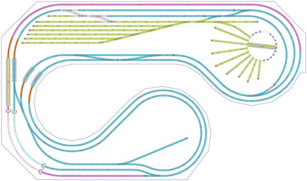
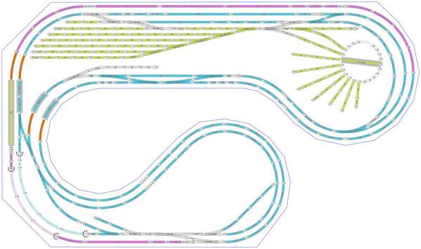
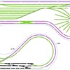
Just an FYI, this version also has a lower bridge elevation than the original, so I changed it to 4" and got a grade of 2.4% on the low side. I also changed the yard switches to #4's just to see what it looked like and maybe free up some space for landscaping. And with that I think we need more guidance from you on where you want to go with the designs. To be sure, there are several versions floating around now.

Capture


Attachments

Images (1)
  • Capture
Files (1)

I took an exact mes. of the with of the room it is 158" wide & I want to stay at 20' (240") long. But I like Jans idea of an 18" isle will give a little more room for industries & landscape. What do you think?

I don't think I can reach the north side (above the Turn Table) of the layout from the access hatch where it is located. I am wondering if I can move the turn table towards the yard  couple of feet & put the hatch around where the TT is located now?

Daz, As far as the bridge elevation goes I just kind of put that in there for visual effect, I am going to keep it @ 3% or less I don't need any clearance under it right now as nothing is running under it. Although I wouldn't mind having a tunnel under it some where.

Daz ,also I right clicked on the file & saved it but the designation numbers on the track & switches is to small to read. I have been playing with it to try to put it into SCARM but can't figure out how.  Can that be done?  If I could read the track numbers then I could just rebuild it myself in Scarm, if I can't just upload to Scarm from the Forum.  


Daz, Jan, I finally got it to upload to the SCARM file. It came in with track & Sw. #'s and all. Thank you all sooooo much for having the patients' to deal with me, it must have been frustrating.

I am so happy & the layout is perfect!

I have most of the Atlas track I need & now I can inventory the track plan & start to acquire the Ross Switches.

 I took a closer look at the access hatch, it will be a long reach but I think I can reach the upper part of the layout from where the hatch is located.

Do you guys think there is any place I could incorporate a couple of tunnels?  

I was working on this version trying to fix some of the track joints when you messages were posted.  I used a half o63 curve to close the divergent track of the O72/O54 switch.  I had also done some work in the yard to improve its operations.  There's now a run-around to help the assembly and breakup of trains.  There's also an alternate entrance to the yard from the inter-loop that avoids the O72/O54 switch.  This is the only O54 curve on the layout.  If you choose hot to have this entrance, O63 will be the controlling curve.  You could then eliminate most of the curve which will allow you to move the turntable to the right.

As to reach all points on the layout, it is not the turntable to worry about provided there is an access hatch to its left..  The place where a 3' reach cannot reach is the back center of the layout.

A mountain with tunnels would work well in the lower left corner and concealing the two mains.  By using multiple smaller bridges a nice river scene with a road on the south side can be incorporated.

Since you indicated that you had a few extra inches in width available you can add a 5.5" straight to the lower end of the orange tracks.  This will allow you to increase the aisle to almost 24".

JanJB O72 V3-jan-daz

Attachments

Images (1)
  • JB O72 V3-jan-daz
Files (1)
Last edited by Jan

I like that Daz. Down the road I am thinking about raising the 2 inner loops going around the South (lower) side of the TT  all the way to the yard spur & the entrance to the yard about  1" to  1 1/2"  & make the upper 3 yard tracks a hump yard along with the main & run around track just to give that a little more visual effect. But I'll have to work on that. What do you think?

Last edited by Jerry Del
Jerry Del posted:

Daz, Jan, I finally got it to upload to the SCARM file. It came in with track & Sw. #'s and all. Thank you all sooooo much for having the patients' to deal with me, it must have been frustrating.
It's never frustrating to help someone who wants to learn. I was doing that since I started working on mainframe computers in the early 70's.

I took a closer look at the access hatch, it will be a long reach but I think I can reach the upper part of the layout from where the hatch is located.
Other than maybe having to remove rolling stock to use it, there's no reason you can't make the far end of the yard a removable access hatch. It takes some extra work and some wiring finesse, but can be done. Will you be able to fit in that triangular section in the corner?

Do you guys think there is any place I could incorporate a couple of tunnels?
Although both Jan and I added some tunnels, I didn't do any measuring to see how much clearance you'll have once you add the walls for the tunnels. I envision something shear like in the photo below or something like the 2nd photo with tracks similar to yours.


Jerry Del posted:

I like that Daz. Down the road I am thinking about raising the 2 inner loops going around the South (lower) side of the TT  all the way to the yard spur & the entrance to the yard about  1" to  1 1/2"  & make the upper 3 yard tracks a hump yard along with the main & run around track just to give that a little more visual effect. But I'll have to work on that. What do you think?

Don't know the grade needed for a hump yard, but here's the TT and yard raised to 1.5" elevation and first 3 down to 0". 

Capture

Capture

Attachments

Images (2)
  • Capture
  • Capture
Files (1)
Last edited by DoubleDAZ

A tweak here, a tweak there, and soon you have a railroad.

ABSOLUTELY my last change(s).  I got rid of the S-curve on the lower left.  I also added a couple of spurs for revenue generating industries. Got to make some money -- and have fun.

I think where I have the tunnel is the best location.  I think raising the out track is a nice touch as it makes for a dramatic exit onto a raised bridge(s).  You'll be able to reach the hidden tracks from the lower left.

What you need to think about are points of interest as you plan your scenery.  Here are a few examples:

  1. The turntable;
  2. The yard;
  3. The tunnel and bridges;
  4. The industries;
  5. Passenger stations; and
  6. A town.

These will attract the attention of your visitors.You will want to add lots of detail.JB O72 V4-jan-daz

I will not make any more changes! Promise!

Jan

PS. A very useful tool in SCARM is the measuring tape.  I use it all the time in conjunction with the enclosed pdf file.  Makes closing gaps fast and easy.

Attachments

I hear you Jan NO MORE CHANGES  Please.   unless you find something that will improve it. 

Jan what is that file Possible Atlas Track links is that all the different sizes track that was used to build the layout?

I have been trying to find the Train Simulator on the SCARM program but can't , can you point me in the right direction?.

Thanks so much again for your help it would have taken me months if at all, to do what you did in 2  or 3 days.  Not only that but your expertise created a layout few people could have.

I already have most of the track I need but I can now inventory the plan and start to accumulate what I need in additional track & Ross Sw's.

When the build out starts I will keep you abreast of it's progress with pix.

Jerry,

The pdf is a listing of the Atlas track sections needed to close a gap of a given length.  Suppose you had a gap of 10.5 inches to fill.  If you look in the table you'll see that 2 x 1.25" + 1 x 1.75" + 1 x 4.5" or you could use 4 x 1.25" + 1 x 5.5" sections.  The tab;e was generated by me many years ago and used the assumption the the fewest number of pieces equated to the lowest cost.  Here's another example:  Suppose you had a gap of 4" to fill.  As you can see there is no entry for 4".  4" has no solution.  But if there is a 10" section at one end of the gap then you look op 14" and use 1 x 1.25" + 1 x 1.75" + 2 x 5.5" pieces.

The reason that I fill the the gaps as completely as possible.  This keeps parallel lines parallel and curves smooth.  You don't want any kinks in the curves,  This will cause  derailment!  For enjoyment you want trains to run without problems.  When you actually lay track you can replace the little pieces with custom cut tracks to reduce joint problems.

When you get to laying track start a new thread.  Then tap your hammer three times and sat "Revealo" and the Forum will give you our secrets.

Jan


Jerry,

In the SCARM menu, select Tools>Parts List. This will create an inventory for you.

To get to simulator, from the Menu, select >Extensions> MTS simulator. You may have to download and install it.

Build concerns, Atlas flex will only bend a very little, like to solve an alignment problem.

Next is the railhead height of Atlas, which is taller than the Ross switches. Rossbed for switch should compensate for this. If any roadbed is used then it will have to be under the switch Rossbed also.

Finally, transitioning from Atlas to Ross will be a small challenge. It's not a plug'n'play deal.

Last edited by Moonman

Thanks Carl; I figured there was a place where the pieces you used were stored I just couldn't find it.  I also have most of the track & so of the Ross switches I am going to use & I have been playing with the height difference but I didn't know the Ross road bed will work thanks. 

Carl those switch signal lights do you buy them directly thru Ross & are you using Tortoise Mach's? 

Thanks   

Last edited by Jerry Del

Jerry, that's Moon's Son - or Moonson  - with the detailed layout

close to Moonman, but it's not me

Using layers in SCARM is easy, but difficult to remember when working on one. The highlighted layer-click on it- in the layers toolbox is where anything added or changed will be.  Uncheck other layers and they will not be displayed in 2D.

To name a layer - select it to highlight it as an active layer - then click on it once more - then the title will be highlighted in a box. Now you can backspace or tap delete to clear it and type in the new name for the layer.

I had a feeling that you had experience working with the Atlas track.

Ok, here's your latest version. I made some tracks bridges so you could see the tracks underneath. I don't have time to look at the rest, but I'll see if I can get some time tomorrow or Sunday night when we stop on the way back to Phoenix.

Note that both the 2D and 3D views are displayed in the post, but the .scarm file is just an attachment. To download, right-click and select Save File As or Save Link As or something similar.

Capture

Capture


Attachments

Images (2)
  • Capture
  • Capture
Files (1)
Last edited by DoubleDAZ

So I have a question. The yard ladder. Isn't the first yard track switch a bad S curve from the lead? My version in pink, is what I keep thinking this lead should look like. Now given there are at least three people posting designs in here with far more experience than myself, I expect I am doing something wrong. Can anyone explain it to me?


And I couldnt help myself so I horsed around with the yard and turntable. (I have never run steam, so I know nothing about turntables). My stuff is blue and pink. original turntable parts are the original color, I just rotated it, and moved it a little.)


Attachments

Images (2)
  • JB2
  • mceclip0
Files (1)
Last edited by 12 monkeys

You shouldn't any problems with your "S-curves."  Your big engines will uncouple from the train and retire to the engine service track.  Your switcher will breakdown the train and sort the cars onto the appropriate spur.

You need to make sure that all your cars are properly weighted:  5 oz + 1 oz per inch of length. 

Jan

My Layout, I changed the yard leads from Ross # 4's to Atlas # 054's. I am going to add Ground throws to the yard instead of Sw. mach's + I have the atlas Sw's I need.

I have also added track elevations 

My Grand Daughter  showed me how to post my Layout. I was not posting it as a jpeg. Thanks Melissa.

Also Many, Many,  thanks to Jan & DoubleDaz for there patient's with me & their help.

Thanks Guys 


Attachments

Images (2)
  • JB 22218 2
  • JB222184
Last edited by Jerry Del

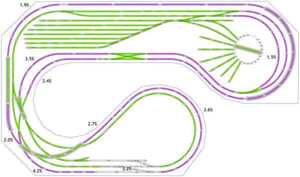
The SCARM file you emailed was slightly different than the one you posted above, but I think I was able to make the changes to make them the same. As you can see, I added the grade percentages so others can see them. I also changed the colors (for illustration purposes only) to separate the flat track (green) from the grade tracks (purple).

I noticed there are a couple of places where you have a track at one grade followed by another track at a different grade rather than combining the 2 for a single smooth grade. Since they are near overpasses, I think that's something you'll have to deal with during the build. I also see that you have 2 switches on overpasses, something else you'll have to deal with during the build to make sure they're supported adequately. I'm a little concerned about the 6" clearance and if it's enough after you add the support, be it a custom bridge or tunnel.

Another concern is your grades start at the switches when I believe conventional wisdom suggests they be started 1 track from the switches and include a transition which would change your grade values. I'm also not sure what the 2 switches that go nowhere are for, maybe future spurs?

I didn't change any track, but I attached this SCARM file as well as yours in case others want to play with it.

Capture


Attachments

I like it, Jan. I'd probably make the trailing switch a curve and just use the left switch for future plans, like a passenger siding or something. I think having to go through 3 switches coming out of the reversing loop is asking for trouble and might require running trains slower through that section. That also might mean no unattended running.

Ok, I noticed the grades and elevations had been changed with all the mods, so I fixed those and redid some of the colors. I also added a couple of spurs to the lower loop. I'm concerned about the 4.9% grade in the lower left. I'm also concerned about some of the flex tracks because my understanding is that Atlas flex is not that flexible. There are also some places where tracks don't join, though they might be close enough for the build. If this is the design we're going to work with now, maybe we can figure how to fix those so we can run the sim.

Capture

Capture


Attachments

Jerry,

Here are some versions of the latest design you emailed. All the joints are now connected and I removed all the flex track, though there are quite a few custom cuts. I reduced it to 2 levels by using a 45° crossover on the black and that made it a lot easier to deal with the purple grades. The minimum curve is now O-63. Photos 1-3 have the outer run elevated 7" like the original. Unfortunately, as we discussed, that reduces the view for a lot of track. I also deleted the 4-way yard switch, but photo 3 shows an alternate yard design using it.

Photos 5-7 shows the same designs with the elevations reversed. Note that the grades changed, but they can probably be adjusted by changing the 4" elevation and/or location of the double-crossover.

Also as we discussed, the double spur to the left of the yard might be too close to the green track. You;re also going to have to deal with all the black track that is either covers the green track or is covered by the green track track.

Capture

Capture

Capture


Capture

Capture

Capture


Attachments

After many weeks of work & emails back & forth I think Dave (doubledaz) came up with a layout plan that has everything  I could ever ask for in a model RailRoad layout. He took my original layout and refined it to where it is as posted.  Cudos to Dave for all the time & effort that went into this very exciting layout. His expertise is second to none.

Thanks  Dave

Jerry 

Add Reply

Post
The Track Planning and Layout Design Forum is sponsored by

AN OGR FORUM CHARTER SPONSOR

OGR Publishing, Inc., 1310 Eastside Centre Ct, Suite 6, Mountain Home, AR 72653
800-980-OGRR (6477)
www.ogaugerr.com

×
×
×
×
Link copied to your clipboard.
×
×