
In August 2010 I started EnzoVille and 7 years later I dismounted.

I had too much humidity in the room and that was the main point.
After a visit from our friend Cesar Buono (My house in Brazil) he helped me make that decision! Thank you Cesar!

Well, let's talk about the new layout!
Here in Brazil we do not have the railway culture, so I do not have where to mirror to create so my expiration is the magazines and the various layouts that I see here in the forum.

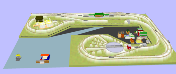
My new space will have 12 x 20 f (380cm x 600cm) and I can not use everything because I need to have space for a maintenance bench among others.

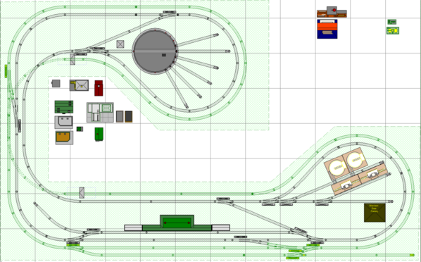
I already have a turntable, MTH passenger station, some work houses, and buildings. I want to keep these items and also a MTH Storage Tank among others.

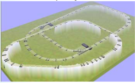
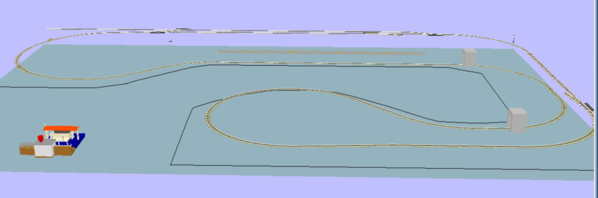
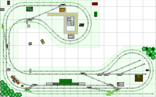
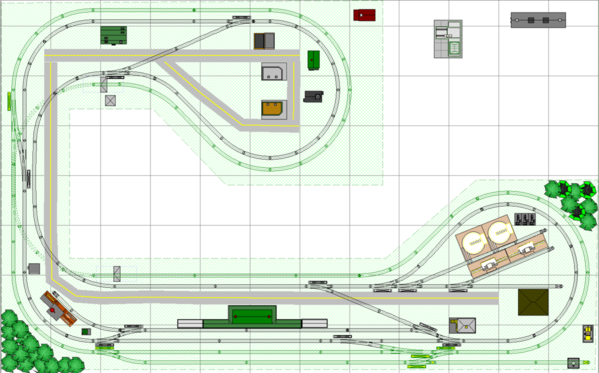
After many hours I was able to create a layout that I am sharing with you and would like help and feel free to comment and change!

My idea is to use Atlas Flex with radius 054 and 063 (I do not have much space for larger spokes) 054 switchs.

I'm still learning to use RRTrack, but something has already come out!

Well I'm waiting for comments and tips.


EnzoVille 2.2

Attachments

Images (1)
  • EnzoVille 2.2
Files (1)
Last edited by Leandro Garcia
Original Post

Replies sorted oldest to newest

Leandro,

Good to see that you have a new one planned. A double track main line is always good. Just do not get too close to the walls. You need enough room engine overhang on the curves and enough room for scenery. You may also want to think about adding some spurs along the way so you can do some switching. Be sure to leave enough room for people to move around. I'm sure others will chime in here with ideas. Great start!


Chris

LVHR


How did you solve the humidity so that you don't have to dismantle this layout too?  

I like the basic layout - maybe some staging tracks, yard tracks for your turntable and sidings?  To accomplish the yard, you might consider putting the turntable on the other leg, as it has a longer approach which is a nice area for yard tracks. 

I very happy the forum, because I always have help from you.

#Chris, thanks for your comments! Surely I will stay away from the walls ! Next works will be to add spurs and different levels. It will be a challenge!

#John, thank you for your comments ! Yes I have that to have, mountains, tunnels, river because my son wants very much.

#PJB,thank you for your comments ! - It will be a brand new space.  I'm going to do this test with the turntable, but I thought in these places to have more space for a city.

Hi Leandro,

I have a few thoughts about working with Atlas track.

You don't really need the 40" Flex straights. They don't flex like HO track.

You can cut any track to a custom length or arc angle. Order item #6057 when you order the track. Those replace the ties when the track is cut and add the snap connectors.

Be sure to order enough extra rail joiners. Good to have in inventory.

Atlas doesn't ship the "short" switches any longer that are listed in the RRT library. Some have a removable piece included to make the "short" version

I believe that you would be happier with #5 turnouts for the crossovers.

Give the Atlas track planning software a try. It supports multiple languages. You may find it easier to learn.

Moonman posted:

Hi Leandro,

I have a few thoughts about working with Atlas track.

You don't really need the 40" Flex straights. They don't flex like HO track.

You can cut any track to a custom length or arc angle. Order item #6057 when you order the track. Those replace the ties when the track is cut and add the snap connectors.

Be sure to order enough extra rail joiners. Good to have in inventory.

Atlas doesn't ship the "short" switches any longer that are listed in the RRT library. Some have a removable piece included to make the "short" version

I believe that you would be happier with #5 turnouts for the crossovers.

Give the Atlas track planning software a try. It supports multiple languages. You may find it easier to learn.

You do not really need the 40 "Flex straights. They do not flex like HO track.
#Carl, you're not the first person to tell me that! I'm going to use 054 and 063 is it best that I buy the curves already in the measure?

You can cut any track to a custom length or arc angle. Order item # 6057 when you order the track. Those replace the ties when the track is cut and add the snap connectors.
#Thanks for this tip I did not know and I will buy.

Be sure to order enough extra rail joiners. Good to have in inventory.
#Yes, I felt it in the old layout.

Atlas does not ship the "short" switches any longer that are listed in the RRT library. Some have a removable piece included to make the "short" version
#But I can remove the straight as I have seen in some pictures.

I believe that you would be happy with # 5 turnouts for the crossovers.
#Sorry, but I did not understand.

Leandro Garcia posted:
Moonman posted:

Hi Leandro,

I have a few thoughts about working with Atlas track.

You don't really need the 40" Flex straights. They don't flex like HO track.

You can cut any track to a custom length or arc angle. Order item #6057 when you order the track. Those replace the ties when the track is cut and add the snap connectors.

Be sure to order enough extra rail joiners. Good to have in inventory.

Atlas doesn't ship the "short" switches any longer that are listed in the RRT library. Some have a removable piece included to make the "short" version

I believe that you would be happier with #5 turnouts for the crossovers.

Give the Atlas track planning software a try. It supports multiple languages. You may find it easier to learn.

You do not really need the 40 "Flex straights. They do not flex like HO track.
#Carl, you're not the first person to tell me that! I'm going to use 054 and 063 is it best that I buy the curves already in the measure?

yes.

You can cut any track to a custom length or arc angle. Order item # 6057 when you order the track. Those replace the ties when the track is cut and add the snap connectors.
#Thanks for this tip I did not know and I will buy.

Be sure to order enough extra rail joiners. Good to have in inventory.
#Yes, I felt it in the old layout.

Atlas does not ship the "short" switches any longer that are listed in the RRT library. Some have a removable piece included to make the "short" version
#But I can remove the straight as I have seen in some pictures.

Yes

I believe that you would be happy with # 5 turnouts for the crossovers.
#Sorry, but I did not understand.

Smaller radius, almost flat switch for mainline crossovers at the top and bottom

I have modified your track plan in the Atlas software. I have Attached the software and the Enzoville layout file.

Here's a 3D:

Enzoville2.2-Moonman_Edit_3D1

I added reversing loops, #5 mainline crossovers. The fitment is somewhat different. I am not sure why you the O54 switch complex in the East.

Anyway, good luck with the rebuild and I hope this provides some ideas.

PS - right-click & save-as for the files.

Attachments

Moonman posted:
Leandro Garcia posted:
Moonman posted:

Hi Leandro,

I have a few thoughts about working with Atlas track.

You don't really need the 40" Flex straights. They don't flex like HO track.

You can cut any track to a custom length or arc angle. Order item #6057 when you order the track. Those replace the ties when the track is cut and add the snap connectors.

Be sure to order enough extra rail joiners. Good to have in inventory.

Atlas doesn't ship the "short" switches any longer that are listed in the RRT library. Some have a removable piece included to make the "short" version

I believe that you would be happier with #5 turnouts for the crossovers.

Give the Atlas track planning software a try. It supports multiple languages. You may find it easier to learn.

You do not really need the 40 "Flex straights. They do not flex like HO track.
#Carl, you're not the first person to tell me that! I'm going to use 054 and 063 is it best that I buy the curves already in the measure?

yes.

You can cut any track to a custom length or arc angle. Order item # 6057 when you order the track. Those replace the ties when the track is cut and add the snap connectors.
#Thanks for this tip I did not know and I will buy.

Be sure to order enough extra rail joiners. Good to have in inventory.
#Yes, I felt it in the old layout.

Atlas does not ship the "short" switches any longer that are listed in the RRT library. Some have a removable piece included to make the "short" version
#But I can remove the straight as I have seen in some pictures.

Yes

I believe that you would be happy with # 5 turnouts for the crossovers.
#Sorry, but I did not understand.

Smaller radius, almost flat switch for mainline crossovers at the top and bottom

I have modified your track plan in the Atlas software. I have Attached the software and the Enzoville layout file.

Here's a 3D:

Enzoville2.2-Moonman_Edit_3D1

I added reversing loops, #5 mainline crossovers. The fitment is somewhat different. I am not sure why you the O54 switch complex in the East.

Anyway, good luck with the rebuild and I hope this provides some ideas.

PS - right-click & save-as for the files.

Carl, Thank you very much !!

Your work was very good and really you gave good ideas.

I'm will install the Atlas software.

I have a doubt. Why use #5 in replace 054 switch?

Thanks !


Last edited by Leandro Garcia

Here is another plan for your 15' X 24' layout space (assuming access to the right).  [your diagram is 15X24, as are your dimensions in centimeters.   Minimum O-63 for the outer route, and O-54 for the inside route, which I left as you specified, perhaps for easier access to the center of the loops.   

There is a siding to the center-left to stop at the station and as a switching lead.   There is route to connect the loops which is O-72 minimum all around the perimeter and over the bridge to the right.   You could build the bridge track on a folding table if you like, or leave it as a long lift-out bridge (must be ridged construction).

Can be expanded, with O-72 minimum for the outer route if you like.   Additional yard tracks can be added at the bottom.  The triangular access and viewing areas are also great places to take photos.

-Ken

M1524A-01_AtlasO_15X24v1b

Attachments

Images (1)
  • M1524A-01_AtlasO_15X24v1b
Last edited by Ken-Oscale
Ken-Oscale posted:

Here is another plan for your 15' X 24' layout space (assuming access to the right).  [your diagram is 15X24, as are your dimensions in centimeters.   Minimum O-63 for the outer route, and O-54 for the inside route, which I left as you specified, perhaps for easier access to the center of the loops.   

There is a siding to the center-left to stop at the station and as a switching lead.   There is route to connect the loops which is O-72 minimum all around the perimeter and over the bridge to the right.   You could build the bridge track on a folding table if you like, or leave it as a long lift-out bridge (must be ridged construction).

Can be expanded, with O-72 minimum for the outer route if you like.   Additional yard tracks can be added at the bottom.  The triangular access and viewing areas are also great places to take photos.

-Ken

M1524A-01_AtlasO_15X24v1b

Ken, 

Fantastico, really a great idea, thank you! ! What program did you use? Can you share the file?

Thanks,

Leandro, I am using AnyRail, which has a free download at AnyRail.com.   You can load and view this plan with the free version, but cannot save any changes (until you purchase the software).   You can hover the mouse over any section of track to see what it is at the bottom of the screen.  Glad you like it!   Here is an improvement along with the AnyRail file.

M1524A-01_AtlasO_15X24v1c

Attachments

Last edited by Ken-Oscale

Go Leandro! What a great idea you have and you're getting lots of great ideas to complement the ones you already have. One question: unless I'm a bad guesser (quite possible) your new room doesn't appear to be twelve feet wide? On closer looks, I'm probably a bad guesser, but I really do like your lighting arrangements. Keep us informed, please. What trains will you run?

Pine Creek Railroad posted:

Leandro,

I agree looks like some serious work is taking place on your train room.   Go with Kens Engineering design, as usual his work is top shelf.

Post some pictures as you build, love to see the work in progress!

This should be a real nice Train Room, remember the dehumidifiers!

PCRR/Dave

Thanks, Dave !

Yes, I remenber the dehumidifiers!

Virginian65 posted:

Go Leandro! What a great idea you have and you're getting lots of great ideas to complement the ones you already have. One question: unless I'm a bad guesser (quite possible) your new room doesn't appear to be twelve feet wide? On closer looks, I'm probably a bad guesser, but I really do like your lighting arrangements. Keep us informed, please. What trains will you run?

Hi ! Thanks !

It is 12.46 x 19.68 ft. I run Lionel Legacy only, but I think in new layout to input DCS MTH !

I would like many things, but I can't to use all space, so I did option to use 054 and 063.


I think in bridges, tunnel, upper and lower, but I don't know how to made all things !


I would ask for help right here! There are some very talented track designers here that make some really nice plans and they like doing it too. Just give them the exact measurements of the space, any other specifics and what you want to have on your layout and they will come up with something for you. 

I am with you, track planning is probably my least favorite part of the hobby and my self designed plans are really terrible. 

rtr12 posted:

I would ask for help right here! There are some very talented track designers here that make some really nice plans and they like doing it too. Just give them the exact measurements of the space, any other specifics and what you want to have on your layout and they will come up with something for you. 

I am with you, track planning is probably my least favorite part of the hobby and my self designed plans are really terrible. 

Thanks !

designed plans are really terrible.....designed plans are really terrible ! Yes me too !


Thanks ! RTR12 !

Mark, yes ! Thanks !

William,

Do you have a plan in mind?  12' x 20'.  I know exactly what I would build.

So, I would like to have everything ! my son want bridge, tunnel, lake, city and industry. I know what not space enough for all this ! 

Room 12' x 19' !

I thought to use 072 for the curves and to try to put the curve up and other down due to lack of room for larger radius (an idea).

Control two trains at the same time and Legacy / DCS.

I already have MTH Station Red other buildings

I was forgetting the Turntable Atlas! (My dream was to change to Millhouse).

Thanks!


Leandro,


While you are still in the planning stage of the layout, take some time and paint the walls BEFORE you put any wood up!  I suggest a Cobalt Blue or similar shade. You can also paint some clouds. The darker blue will really make the clouds "pop". There are numerous tutorials on the web about how to do this. Jim Barrett had an article near the beginning of his building a layout series that explained it as well. The nice thing is if you don't like your work, you simply paint over it! By the way, MUCH easier to do this when there is no layout in the way.... Just figure out how high the layout will be and go from there.


Chris

LVHR

The problem of eliminating humidity looks like it hasn't been solved so here is what I do.  My layout is in a high humidity location (basement) and during the summer I use a dehumidifier to dry the air. During winter its cold up here and the furnace is running so there is little humidity in the basement. IMO, you've got to keep the humidity below 50% to prevent rust and erosion.

Nice design, have you thought about keeping the 2 lines separate.  Maybe a siding or small 2 track staging yard on the longer end of the dog bone. I am in the same spot as you, we bought a different house and in the process of redoing the future train room. I like the idea of a giant dog bone shape bent back onto itself. I will be following your progress. Nick T.  

Okay, Leandro, here you go, I hope this is what you were trying to get. If it is, your problem was you were trying to draw the table outline using the Object/Basic Shapes/Polygon tool and that doesn't work for what you want. You have to use the Action/New Base/Poly tool in the Terrain View to draw a New Base. That's how you get it to display the white heights to show elevations. Hope this helps.

Edit: Looking at your plan though, the part you have elevated (Red in 2nd photo) is connected to the lower part at the crossovers on the left and bottom, so that will not work. You also have some Blue track crossing over other tracks at the same height, so that will not work. You may have wanted these reversed, but they didn't come out that way.

Capture

 Capture


Attachments

Images (2)
  • Capture
  • Capture
Files (1)
Last edited by DoubleDAZ

leandro,

The lack of good 3D in RR-T makes this difficult. I can see that when you build, the center loop will be at a lower height. I tried raising all track and buildings to 15.50cm and then setting a grade off the center straight. The track would descend into a tunnel and then out again. So, I set that track 0.00cm. Grade track is in red. ~ 5%

The 3D is still very poor.

It will look nice when you build. Adjust the framing to accommodate the grade below the main table height.

Now, to find places for the rest of the accessories and buildings.

EnzoVille 2.4_2018-DAZ_Moonman

Attachments

DoubleDAZ posted:

Okay, Leandro, here you go, I hope this is what you were trying to get. If it is, your problem was you were trying to draw the table outline using the Object/Basic Shapes/Polygon tool and that doesn't work for what you want. You have to use the Action/New Base/Poly tool in the Terrain View to draw a New Base. That's how you get it to display the white heights to show elevations. Hope this helps.

Edit: Looking at your plan though, the part you have elevated (Red in 2nd photo) is connected to the lower part at the crossovers on the left and bottom, so that will not work. You also have some Blue track crossing over other tracks at the same height, so that will not work. You may have wanted these reversed, but they didn't come out that way.

Capture

 Capture


Dave, Thank You !

That's exactly what I wanted to do.

My idea is to do all way up for 15 cm height and green track external for 0 cm.
But I don't have a idea this is the best to do.
I'm trying to create my layout and I don't like to have only one level I like to have 3 level, but I'm having many difficulty this.
Thank you your help !


Moonman posted:

leandro,

The lack of good 3D in RR-T makes this difficult. I can see that when you build, the center loop will be at a lower height. I tried raising all track and buildings to 15.50cm and then setting a grade off the center straight. The track would descend into a tunnel and then out again. So, I set that track 0.00cm. Grade track is in red. ~ 5%

The 3D is still very poor.

It will look nice when you build. Adjust the framing to accommodate the grade below the main table height.

Now, to find places for the rest of the accessories and buildings.

EnzoVille 2.4_2018-DAZ_Moonman

Carl,

Yes ! This my idea, but I don't know this is the best idea ! That's what I said to Dave!

If you had another idea it will be welcome !

Thank you your help !


DoubleDAZ posted:

Nice change Jan. I'd also consider switching around the road and the passenger station so passenger trains don't foul the mainline while loading/unloading. The short spur on the left can be extended by using 2 curved pieces in place of the half-curve.

Dave, sorry but I didn't understand your changes.
Can you show me where it's?
 
Thanks!
Moonman posted:
Leandro Garcia posted:
Jan posted:

I rearranged the track at the bottom which I thinl will improve operations.

Jan

EnzoVille 2.4_2018-DAZ_Moonman_Jan

Jan, Thank you for your changes ! I liked and now I can think in to elevate external to 20 cm or more !

I don't see where you can elevate the green line to make it useful. The switch tie -ins to the black on the left and at the bottom pin down the green line to black line height.

The green line from 8 o'clock to 4 o'clock at the bottom would be elevated. This would block the view of the yard and accessories.

Here is my fixes. The switches connecting the green line and black line were removed. Assume that the black line is at 0cm height. The green line climbs from the tunnel at -15.50cm to 0cm, then climbs to +15.50cm around the roundhouse on open trestle to land on the straight. it is on land all the way around to the opposite corner, where it descends to 0cm on open trestle again , then descends in the tunnel under the black line at 9 o'clock to -15.50cm.

The black line needs the 4-way crossover at 9 o'clock as in an above version. The green line will not be able to change direction on the run.

This provides the elevation look that you want at the cost of disconnecting the green from the black line.

EnzoVille 2.4_2018-DAZ_2_Moonman_2DEnzoVille 2.4_2018-DAZ_2_Moonman_3D

Jan, I understand I was wrong for I not want disconnect both tracks !
Thank you !

Leandro,

Those were my changes for another idea - I quoted your answer to Jan's changes. I will keep them separate.


I don't see where you can elevate the green line to make it useful. The switch tie -ins to the black on the left and at the bottom pin down the green line to black line height.

The green line from 8 o'clock to 4 o'clock at the bottom would be elevated. This would block the view of the yard and accessories.

Here is my fixes. The switches connecting the green line and black line were removed. Assume that the black line is at 0cm height. The green line climbs from the tunnel at -15.50cm to 0cm, then climbs to +15.50cm around the roundhouse on open trestle to land on the straight. it is on land all the way around to the opposite corner, where it descends to 0cm on open trestle again , then descends in the tunnel under the black line at 9 o'clock to -15.50cm.

The black line needs the 4-way crossover at 9 o'clock as in an above version. The green line will not be able to change direction on the run.

This provides the elevation look that you want at the cost of disconnecting the green from the black line.

EnzoVille 2.4_2018-DAZ_2_Moonman_2DEnzoVille 2.4_2018-DAZ_2_Moonman_3D

Attachments

Hi Leandro,

Yes, that is a good decision.

I cannot get the answer that I want from RR-Track. I believe that you have too much of the end semicircle behind the city as grade track. If a quarter of that can be left at the main level height, more space for the city can be created. A road could cross the two lines and disappear at wall and table corner. More scenic items can be added.

If you wish to have a turntable/roundhouse in the future, the yard area could be reworked. You could also added more spurs for engine storage. How you use the layout will tell you if you need any changes.

I will try to convert the track plan to SCARM to enable a better 3D view to demonstrate your layout.


PS: Sorry about the World Cup results. We weren't even there.


Carl, there are other problems with the upper grade too. I don't know if you noticed, but the section by Red line was 1.37" high and the original grade started there. It ran just around the half circle and was almost 5%. On the other side of the Red line the elevation is 0" and abruptly went up to the 1.37". The lower grade was also almost 5%, so I added some tracks to both grades (Purple) to get them down to around 3%. They can both be extended further to get them a little lower.

FWIW, I also agree with deleting the turntable, but that's because I don't intend to collect engines and, like Leandro, I don't have room for a "real" yard complete with roundhouse, engine repair facility, lead tracks, etc.

Capture


Attachments

Images (1)
  • Capture
Moonman posted:

Hi Leandro,

Yes, that is a good decision.

I cannot get the answer that I want from RR-Track. I believe that you have too much of the end semicircle behind the city as grade track. If a quarter of that can be left at the main level height, more space for the city can be created. A road could cross the two lines and disappear at wall and table corner. More scenic items can be added.

If you wish to have a turntable/roundhouse in the future, the yard area could be reworked. You could also added more spurs for engine storage. How you use the layout will tell you if you need any changes.

I will try to convert the track plan to SCARM to enable a better 3D view to demonstrate your layout.


PS: Sorry about the World Cup results. We weren't even there.

Carl, Thanks !

Carl, Thanks !

I'm still deciding how make my benchwork ! I don't know if I create all benchwork at a higher or lower height because I want difference high plains.

A road could cross the two lines and disappear at wall and table corner" Yes ! I had thinking therein.

DoubleDAZ posted:

Carl, there are other problems with the upper grade too. I don't know if you noticed, but the section by Red line was 1.37" high and the original grade started there. It ran just around the half circle and was almost 5%. On the other side of the Red line the elevation is 0" and abruptly went up to the 1.37". The lower grade was also almost 5%, so I added some tracks to both grades (Purple) to get them down to around 3%. They can both be extended further to get them a little lower.

FWIW, I also agree with deleting the turntable, but that's because I don't intend to collect engines and, like Leandro, I don't have room for a "real" yard complete with roundhouse, engine repair facility, lead tracks, etc.

Capture


Dave, Thanks,

"I also agree with deleting the turntable, but that's because I don't intend to collect engines and, like Leandro, I don't have room for a "real" yard complete with roundhouse, engine repair facility, lead tracks, etc."  Exactly ! My friend and my father open my eyes about turntable...but I think to create small repair for locomotives .....


Hi Leandro,

The dwarf signal is used to indicate switch position and in yards. Because it is short, it is for low speed areas. Most place them near a switch and hook to the switch controller to change the aspect color. Through is green, Red is diverging. This is relative to your mainline path.

The tall signals are for main line use. They are for train speed control. Red is stop and wait for orders, yellow has different rules, but is like slow, proceed with caution and green is maximum speed for that area or by railroad rules.

Most will place a couple on the mainlines where visitors can see them to mimic traffic control. They are usually green when  a train approaches a signal block, the train triggers the relay when it enters the block, then it turns red for time, then yellow, then green again when the train has cleared the block.

You can search them forum for threads on the ways to control the signals.


Last edited by Moonman
Moonman posted:

Hi Leandro,

The dwarf signal is used to indicate switch position and in yards. Because it is short, it is for low speed areas. Most place them near a switch and hook to the switch controller to change the aspect color. Through is green, Red is diverging. This is relative to your mainline path.

The tall signals are for main line use. They are for train speed control. Red is stop and wait for orders, yellow has different rules, but is like slow, proceed with caution and green is maximum speed for that area or by railroad rules.

Most will place a couple on the mainlines where visitors can see them to mimic traffic control. They are usually green when  a train approaches a signal block, the train triggers the relay when it enters the block, then it turns red for time, then yellow, then green again when the train has cleared the block.

You can search them forum for threads on the ways to control the signals.


Carl !

Thank you !

Leandro Garcia posted:
Mark Boyce posted:

Leandro,

That is a great start!  I see your inspector is right in the middle of things!!   Or is she the master carpenter?  

Mark Thanks ! Yes ! She is inspector and she want the fast construction !

That looks like a great start and I bet that has to be exciting to you as well.

I bet the inspector is in a hurry to move up from inspector to train engineer.  

That's a great age for inspectors and engineers, enjoy them while you can before they grow up!

Last edited by rtr12
Rescued Trains posted:

Hello Leandro, I've been following your progress since the start. I am curious what species of wood is your bench work made from. It seems very straight and somewhat free from knots and imperfections.

Steve

Hi, Steve ! Thanks !

So, In Brazil the name this Wood is " Pinus " and I Think in EUA " the name is " Pine Wood" . I bought in big Store " Leroy Merlin" the similar the Home Depot or Lowes !
I like much !


Mark Boyce posted:

Leandro, Well the Pine looks better than what I see at Lowe’s and Home Depot!  LOL

That is great progress!  I see a Canyon on the end for a trestle I presume!  Yet another helper caught in the middle!!  LOL  looks like they are enjoying helping you!!  That is huge!

Mark,

I do the relay with my assistants! Enzo did holes, screwed and he liked !

Yes, My Canyon will be my big challenge ! 
Thanks !

Looking at the photos, did you plan for electrical outlets? I only found one and it looked like it was hidden by some bench work.

Otherwise looks like you are making great progress.  Just don't take short cuts in the rush to get trains running,  You and your son will have plenty of time to enjoy them when everything is done just right to your satisfaction.

Suggest that you place your biggest engine on the curves near the walls and tunnels to check that any overhang will not hit them.  Check the overhang running engine in both directions,  Also check overhang with engine backing up, as some engine cabs will shift position and stick out to hit wall or tunnel edges.  Easy to adjust roadbed and tunnel openings now before all track is fastened permanently.  (Ask me how I know about engine overhang hitting wall problems )

rrman posted:

Looking at the photos, did you plan for electrical outlets? I only found one and it looked like it was hidden by some bench work.

Otherwise looks like you are making great progress.  Just don't take short cuts in the rush to get trains running,  You and your son will have plenty of time to enjoy them when everything is done just right to your satisfaction.

Suggest that you place your biggest engine on the curves near the walls and tunnels to check that any overhang will not hit them.  Check the overhang running engine in both directions,  Also check overhang with engine backing up, as some engine cabs will shift position and stick out to hit wall or tunnel edges.  Easy to adjust roadbed and tunnel openings now before all track is fastened permanently.  (Ask me how I know about engine overhang hitting wall problems )

RRman, 

In photos not show, but I have 10 electrical outlets !

I had the same problem with my Big Boy in wall at my first layout and now will be my first test!

I like to draw. Couldn't pull off a flexing S. An S presents rollercoaster type track issues if you change the grade. An S must stay flat. A straight allows a twist/tilt transition time. The coupler angles are opposing; one faces left, one faces right, fighting to drag or be dragged off the rails. (Lionel couplers DO vary slightly in size over the years. This may or may not be an issue at the moment. Long cars really don't like them.

I use a rough cut 2x4" with a 1/8" strip of paneling as a clearance guide. Where I forgot to hold the panel to the 2x4 my E-33 handrail bumps the wall.   

A locomotive snow plow took out a foam porch once.

Because of my not considering backdrop thickness (1/8th" tops), four spots on 3 layouts get clipped with some locos.   The roofs I count seperately; cab roofs with big overhang; 2 spots one layout. Tunnels; 3 spots, two on long cars, one on a portal by a Berk cab's roof. 

Adriatic posted:
Ooops. I'm not entirely sure its my fault though. I'm having serious browser issues today. I think it closed the other page and added that post here... I'll clean up soon, but right now the edit and attachment tools are too angry.

Adriatic, Thank you !

I had the same problem in my first layout I had to dig a hole in wall !!

Attachments

Images (1)
  • mceclip0
Leandro Garcia posted:
Moonman posted:

Ola Leandro,

I saw this climbing curve as an exposed curve next to a cliff. Are you making it a tunnel?

IMG_20181120_172059987

Yes, but it's still missing construction and a bridge in curve until tunnel !

Leandro Garcia posted:
Moonman posted:

leandro,

I am still confused.  I thought that the outside line went from the low level to the upper level? 

Did you change the track plan?

Trestle_end_2018.12.3


Carl,

You is right ! This photo is not show the correct  upper level access. The next steps I will show !

I can see the low base for the canyon. I was surprised when I saw the curved template clamped to the main level. The template is good idea!

Like Mark stated earlier, we pay a premium for clear pine and there are still small knots. That's nice wood to build with that you have.

Last edited by Moonman
Moonman posted:
Leandro Garcia posted:
Moonman posted:

Ola Leandro,

I saw this climbing curve as an exposed curve next to a cliff. Are you making it a tunnel?

IMG_20181120_172059987

Yes, but it's still missing construction and a bridge in curve until tunnel !

Leandro Garcia posted:
Moonman posted:

leandro,

I am still confused.  I thought that the outside line went from the low level to the upper level? 

Did you change the track plan?

Trestle_end_2018.12.3


Carl,

You is right ! This photo is not show the correct  upper level access. The next steps I will show !

I can see the low base for the canyon. I was surprised when I saw the curved template clamped to the main level. The template is good idea!

Like Mark stated earlier, we pay a premium for clear pine and there are still small knots. That's nice wood to with that you have.

Carl,

My idea from canyon is to try to do the trestle bridge that inspiration in bridge of the Alex (Ingeniero No1) ! OGR 256! 


Attachments

Images (1)
  • mceclip0

I am not sure that the trestle will work. Those trestles are level. You need a grade rising from low level to the top level. trying to make the bents for a grade will complicate building it.

Did Alex demonstrate how he made the bents in the article? He has a lot of woodworking skill and professional tools. If he did not, I can link you to his layout build thread. He explains the process there.

A layout build thread by Darren Caruso also has a trestle on an end curve. The track is level. 

You can support the sub-roadbed with risers to get the layout running. The permits working on terrain or the trestle as another project.


Leandro Garcia posted:
Moonman posted:

Doesn't the end in the RR-Track plan look something like this?


Carl,
Exactly this which I thought but I not had success in my project RRtrack I'm still a baby in it.
Your draw is perfect with my mind !

Leandro,

Ok. I made that with SCARM. The 3D is better.

I think that if you make the bents equal height that you can adjust for the grade with blocks at the bottom. It may make some of the outside interlocking diagonal supports tricky.

Measure your reach - standing straight and arm out level - from your chest to your wrist. (what's your shirt sleeve length?)

Now measure that from the edges of the table.  Move around and try a different position to reach a place.

Any places that you cannot reach?

I am thinking all solid deck. Then, only the sides will need rock faces or scenery.

Where is this? The center of the "U" shape?

All of the curves on the lower level should be curving away from the upper level except for the grades on the end.

A diagonal brace will support that area - on a 45 degree angle 

Can you post the track plan that you are using - you can print from RR-Track.

I have this:Enzoville2.7_60.50.2018

Enzoville_2.7_6050_2018

Attachments

Images (1)
  • Enzoville_2.7_6050_2018
Moonman posted:

Where is this? The center of the "U" shape?

All of the curves on the lower level should be curving away from the upper level except for the grades on the end.

A diagonal brace will support that area - on a 45 degree angle 

Can you post the track plan that you are using - you can print from RR-Track.

I have this:Enzoville2.7_60.50.2018

Enzoville_2.7_6050_2018

Yes, " U " shape in lower level !

Thanks !

It looks to me the semi-circle center should be between the front and rear supports indicated by the yellow arrows.

Assemble the left and right half of the semi-circle and insert from each side in between the supports. On the track plan, it appears to be 6" from the wall. Then observe the track position. The ends of the semi-circle should be positioned to set each side for the beginning of the grade. 

Enzoville_2.7_6050_2018

Attachments

Images (1)
  • Enzoville_2.7_6050_2018

This company, MicroFasteners has #4 x 3/4" in black oxide 100pcs for $3.90 US. Their minimum shipping for international orders is $7.00.So, that's 100 screws for the price of 48 Atlas screws

In RR-Track, Component view displays the layout parts - the track count is 235 x 2 screws per track =700

I searched for sheet metal screws with black oxide coating suppliers in brazil with no luck - stainless only - very expensive


Use 1 screw per track until you get more screws to continue assembly - one at each joint

Last edited by Moonman
Moonman posted:

This company, MicroFasteners has #4 x 3/4" in black oxide 100pcs for $3.90 US. Their minimum shipping for international orders is $7.00.So, that's 100 screws for the price of 48 Atlas screws

In RR-Track, Component view displays the layout parts - the track count is 235 x 2 screws per track =700

I searched for sheet metal screws with black oxide coating suppliers in brazil with no luck - stainless only - very expensive


Use 1 screw per track until you get more screws to continue assembly - one at each joint

Carl, Thanks a lot !!!

The straight track in the center was not in the track plan. Remember that this track will set the ends of the semi circle to align with the grade tracks.

I suggest that work on the upper level main line, the grades on each side, then align this curve by adjust that straight.

The work looks good as it always does. Is pai working with you?


Attachments

Images (1)
  • mceclip1
Moonman posted:

The straight track in the center was not in the track plan. Remember that this track will set the ends of the semi circle to align with the grade tracks.

I suggest that work on the upper level main line, the grades on each side, then align this curve by adjust that straight.

The work looks good as it always does. Is pai working with you?


Carl, 

The track was there ! Can you see in my track plan ! I think up level track is blocking your vision.

Other question ! What AWG of the wire I should use? I will use two power Lionel 180W only track and Legacy system.

Thanks,

Attachments

Images (1)
  • mceclip0

YES, I MISSED THAT TRACK!   Ok , you should only have get the side to side alignment after you bring the grade track down. 

Lay the upper level mainline from the center crossover out to the grade. Then, work on the grade supports and sub-roadbed.

I don't know what wire sizes are available to you. I use a 12 awg bus with 16 awg track feeds for Legacy. Only one common is needed and two HOT. The transformers connect to the one common. All 14awg is suitable, but the 14 is a little heavy to work with for track feeds. So, a 14 awg bus and 16 awg  track feeds can work.

Basically, whatever you can at a reasonable price. Wire prices have increased in the U.S. 

Leandro Garcia posted:

Hi !!

Last Updates !


Where do you get the elevation points (heights) for the grade? I don't remember what the slope was for that or how to find it in RR-Track.

Edit- ok - I see that if the mouse cursor is hovered over a track joint, the elevation is displayed.

It will look great with a train sweeping around it. 

A train will put on a good shown running the outer loop up mainline and down and under the center.

Last edited by Moonman

Leandro, Picking up on Andy's comment, which I agree your benchwork looks great, aroused my curiosity.  You probably have read where we have trouble getting dimensional lumber here in the United States and Canada that is suitable for benchwork, wood that won't warp, twist, etc.  So, do you have that problem in Brazil, and what can you tell us about the wood you used?

Moonman posted:
Leandro Garcia posted:

Hi !!

Last Updates !


Where do you get the elevation points (heights) for the grade? I don't remember what the slope was for that or how to find it in RR-Track.

Edit- ok - I see that if the mouse cursor is hovered over a track joint, the elevation is displayed.

It will look great with a train sweeping around it. 

A train will put on a good shown running the outer loop up mainline and down and under the center.

Carl, I take elevation points in RRtrack in grades !

Thank You !!

Mark Boyce posted:

Leandro, Picking up on Andy's comment, which I agree your benchwork looks great, aroused my curiosity.  You probably have read where we have trouble getting dimensional lumber here in the United States and Canada that is suitable for benchwork, wood that won't warp, twist, etc.  So, do you have that problem in Brazil, and what can you tell us about the wood you used?

Andy, Thank you !

Mark, Thank you ! So I found wood in Leroy Merlin the same that the Lowes and Home Depot . There I found dimensional to wood !

My problem now with insulation foam board !

Last edited by Leandro Garcia

The children are growing up too fast!  You have been a forum friend for a long time now.

You will be happy with the multi-level design.

Perhaps a test run of a diesel to check the grade - jumpers clips for power - make a climb and descent run

Do you think you will be able to acquire the insulation board for the ground/earth?  I don't recall how that was before foam board. The construction style is like open grid with risers of L-girder style. I will research or perhaps others can tell you other methods.

Moonman posted:

It is beginning to come alive! The track testing crew was having fun!

Are you dropping track feeders as to go along or laying the track only?

Have you been able to locate foam board or do you want to use alternative methods? 

Carl, Thank you !

Yes! My children was having fun !

** Are you dropping track feeders as to go along or laying the track only? ** Sorry I not understand ! **

I found XPS same foam board, tonight I will put the picture here.

Moonman posted:

The EPS will work well. Easier than traditional methods. 

I was asking about the 2 track power wires at various points to supply the track power. Are you installing those as you lay the track?

Ahhh, Sorry ! I didn't know " track feeders" !!

No I not put wires yet, because I not screwed the track and I miss to put track-bed ! I'm testing tracks first.

I have a question the power track wires I would ask about this, because here in Brazil my friends recommended to put each 40 inch red wire/black wire and alternate black wire side. Is this correct?

I think about using two Lionel power 180W only to tracks.

Thanks!

Ok, I understand. This is a track fitment stage.

The wiring method suggested to you sounds ok. I like alternating the common wire to have both outside rails with common. Every 40 inches may be too many.

I use a 120 inch - 144 inch spacing between power connections.

How did you do it on the previous layout? It was operating properly before it was disassembled, yes?

How do you connect the 180 watt transformers? Did you make an adapter wire for the Molex plug or did you cut it off? I am asking because I want to be sure that you can identify the Hot (red) and the Common (black) wires of the 180 watt transformer.

Moonman posted:

Ok, I understand. This is a track fitment stage.

The wiring method suggested to you sounds ok. I like alternating the common wire to have both outside rails with common. Every 40 inches may be too many.

I use a 120 inch - 144 inch spacing between power connections.

How did you do it on the previous layout? It was operating properly before it was disassembled, yes?

How do you connect the 180 watt transformers? Did you make an adapter wire for the Molex plug or did you cut it off? I am asking because I want to be sure that you can identify the Hot (red) and the Common (black) wires of the 180 watt transformer.

I like your suggestion 120 inch! I thought that 40 inch many too!
Do you welded all connection tracks (between tracks)?

In my previous layout was very bad ! I had only 4 track-feeders ! 

I have two Lionel Direct TMCC/Legacy (6-34120). In my previous layout I used only one.

Leandro Garcia posted:
Moonman posted:

Ok, I understand. This is a track fitment stage.

The wiring method suggested to you sounds ok. I like alternating the common wire to have both outside rails with common. Every 40 inches may be too many.

I use a 120 inch - 144 inch spacing between power connections.

How did you do it on the previous layout? It was operating properly before it was disassembled, yes?

How do you connect the 180 watt transformers? Did you make an adapter wire for the Molex plug or did you cut it off? I am asking because I want to be sure that you can identify the Hot (red) and the Common (black) wires of the 180 watt transformer.

I like your suggestion 120 inch! I thought that 40 inch many too!
Do you welded all connection tracks (between tracks)?

In my previous layout was very bad ! I had only 4 track-feeders ! 

I have two Lionel Direct TMCC/Legacy (6-34120). In my previous layout I used only one.

I like the "screw-it" method for Atlas track used by Ingenerio 1. A small hole is drilled in the base of the rail and the wire is inserted into the hole. It is sercured with a #1 sheet metal screw.

I can link the method to you if you wish to use it. 

Soldering to the bottom of the rail is good. The black needs to be removed from the center rail and a special flux used for the nickel-silver alloy.

let me know about the screw-it method.

Moonman posted:
Leandro Garcia posted:
Moonman posted:

Ok, I understand. This is a track fitment stage.

The wiring method suggested to you sounds ok. I like alternating the common wire to have both outside rails with common. Every 40 inches may be too many.

I use a 120 inch - 144 inch spacing between power connections.

How did you do it on the previous layout? It was operating properly before it was disassembled, yes?

How do you connect the 180 watt transformers? Did you make an adapter wire for the Molex plug or did you cut it off? I am asking because I want to be sure that you can identify the Hot (red) and the Common (black) wires of the 180 watt transformer.

I like your suggestion 120 inch! I thought that 40 inch many too!
Do you welded all connection tracks (between tracks)?

In my previous layout was very bad ! I had only 4 track-feeders ! 

I have two Lionel Direct TMCC/Legacy (6-34120). In my previous layout I used only one.

I like the "screw-it" method for Atlas track used by Ingenerio 1. A small hole is drilled in the base of the rail and the wire is inserted into the hole. It is sercured with a #1 sheet metal screw.

I can link the method to you if you wish to use it. 

Soldering to the bottom of the rail is good. The black needs to be removed from the center rail and a special flux used for the nickel-silver alloy.

let me know about the screw-it method.

Carl,

I think interesting I remembered this post when he did !  
I no have idea if I will find this screw here ! I think I will have to import this screw the website MicroFasterners !

***special flux used for the nickel-silver ** 

Thanks,

Leandro Garcia posted:
Moonman posted:
Leandro Garcia posted:
Moonman posted:

Ok, I understand. This is a track fitment stage.

The wiring method suggested to you sounds ok. I like alternating the common wire to have both outside rails with common. Every 40 inches may be too many.

I use a 120 inch - 144 inch spacing between power connections.

How did you do it on the previous layout? It was operating properly before it was disassembled, yes?

How do you connect the 180 watt transformers? Did you make an adapter wire for the Molex plug or did you cut it off? I am asking because I want to be sure that you can identify the Hot (red) and the Common (black) wires of the 180 watt transformer.

I like your suggestion 120 inch! I thought that 40 inch many too!
Do you welded all connection tracks (between tracks)?

In my previous layout was very bad ! I had only 4 track-feeders ! 

I have two Lionel Direct TMCC/Legacy (6-34120). In my previous layout I used only one.

I like the "screw-it" method for Atlas track used by Ingenerio 1. A small hole is drilled in the base of the rail and the wire is inserted into the hole. It is sercured with a #1 sheet metal screw.

I can link the method to you if you wish to use it. 

Soldering to the bottom of the rail is good. The black needs to be removed from the center rail and a special flux used for the nickel-silver alloy.

let me know about the screw-it method.

Carl,

I think interesting I remembered this post when he did !  
I no have idea if I will find this screw here ! I think I will have to import this screw the website MicroFasterners !

***special flux used for the nickel-silver ** 

Thanks,

***special flux used for the nickel-silver ** 

yes, search for "flux for nickel-silver"  or "flux for silver jewelry" it is a white colored flux because of the minerals in it

The Atlas O rails are made of a nickel silver alloy - using regular flux or rosin core solder or newer flux core solder will make for a difficult time of soldering.

Moonman posted:
Leandro Garcia posted:
Moonman posted:
Leandro Garcia posted:
Moonman posted:

Ok, I understand. This is a track fitment stage.

The wiring method suggested to you sounds ok. I like alternating the common wire to have both outside rails with common. Every 40 inches may be too many.

I use a 120 inch - 144 inch spacing between power connections.

How did you do it on the previous layout? It was operating properly before it was disassembled, yes?

How do you connect the 180 watt transformers? Did you make an adapter wire for the Molex plug or did you cut it off? I am asking because I want to be sure that you can identify the Hot (red) and the Common (black) wires of the 180 watt transformer.

I like your suggestion 120 inch! I thought that 40 inch many too!
Do you welded all connection tracks (between tracks)?

In my previous layout was very bad ! I had only 4 track-feeders ! 

I have two Lionel Direct TMCC/Legacy (6-34120). In my previous layout I used only one.

I like the "screw-it" method for Atlas track used by Ingenerio 1. A small hole is drilled in the base of the rail and the wire is inserted into the hole. It is sercured with a #1 sheet metal screw.

I can link the method to you if you wish to use it. 

Soldering to the bottom of the rail is good. The black needs to be removed from the center rail and a special flux used for the nickel-silver alloy.

let me know about the screw-it method.

Carl,

I think interesting I remembered this post when he did !  
I no have idea if I will find this screw here ! I think I will have to import this screw the website MicroFasterners !

***special flux used for the nickel-silver ** 

Thanks,

***special flux used for the nickel-silver ** 

yes, search for "flux for nickel-silver"  or "flux for silver jewelry" it is a white colored flux because of the minerals in it

The Atlas O rails are made of a nickel silver alloy - using regular flux or rosin core solder or newer flux core solder will make for a difficult time of soldering.

Carl,

I really not know to do this ! I must use the flux in track and after I weld with soldering tin normally? It's that? 

I think that option screw is better ! But my problem will be to find the screw in Brazil!

Thanks,

Leandro Garcia posted:

Hi, Guys !

Update of the last post !

My question ! What steps I should work?

  • Put track bed;
  • Works in power distribution for track and switches;
  • Works in my Bridge 


I like those steps - roadbed down - then, you may have put holes in roadbed for wiring - therefore, wiring next or do you mean that you are going put ballast (stones) down now and the track is already on the roadbed? If that what you will do next- then connect the wiring first - and then apply the ballast.

I am not sure what you need to do for the bridge- are you speaking of the trestle curve?

Great progress! 

Moonman posted:

yes, indeed! That is a nice trestle!

I prefer the open stringers with the track ties on top - it's a scary look down through the track.

Decks on the stringers are prototypical, so no problem with that - especially after all of that routing.

Carl, I also prefer!
But I made a biggest trestle for both tracks external and internal, so I 'm going to have others small trestle only internal track and therefore I had to made a biggest trestle !

I would recommend 7 inches or 17.78cm from the lower track railhead to the bottom of the overpass wood.

You can have less if it is not available. Measure the height of the tallest engine or car that you have. That will be the limit. 

Double stacked container cars and auto rack (carrier) cars tend to be the tallest.

I am sorry that I didn't comment on the trestles - I had a loss in the family and the holidays were a bit tough. The result looks really great!

Last edited by Moonman

Add Reply

Post
The Track Planning and Layout Design Forum is sponsored by

AN OGR FORUM CHARTER SPONSOR

OGR Publishing, Inc., 1310 Eastside Centre Ct, Suite 6, Mountain Home, AR 72653
800-980-OGRR (6477)
www.ogaugerr.com

×
×
×
×
Link copied to your clipboard.
×
×