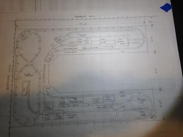
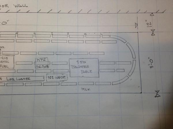
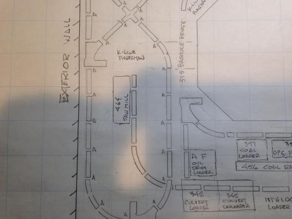
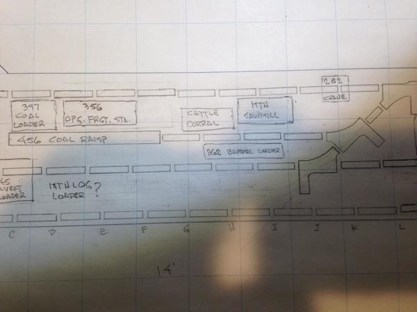
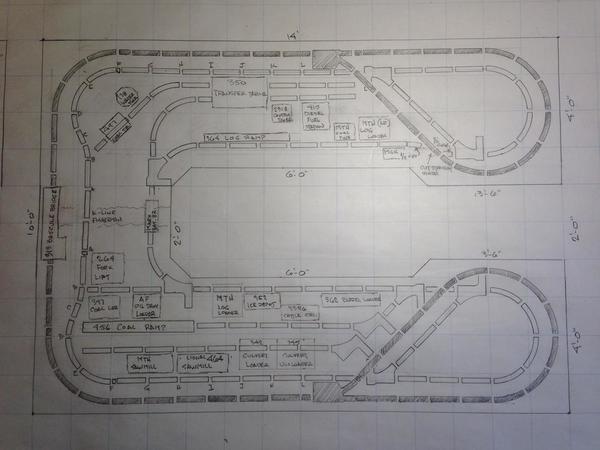
I'm in the process of designing my layout to be.  Still have at least a year before it gets started.  I wonder if anyone here would care to come up with a layout based on the following criteria.  At the moment, I have no plans to award a prize, other than to visit the layout and my garden railway when the layout is completed..... 

Here is the design criteria;

Tubular track throughout. Plenty of O22 switches and four O72 switches on hand.

I have a 10 x 14 foot area to work with.  The room is larger than the layout size to allow for walk around space on at least three sides.

The following accessories must be included.

1. Lionel 282 Gantry crane

2. MTH 23796 Sawmill.  Remake of the American Flyer mill

3. Lionel 6-2318 Control tower

4. Lionel 494 Beacon

5. MTH Dispatch board.  Remake of Lionel 334

6. Lionel Oil derrick

7. Lionel 313 Bascule bridge

8. Lionel Oil drum loader.  Remake of the AF version

9. Lionel 6-22999 Dispatch station

10. Lionel 6-19800 Cattle corral

11. Lionel 19818 Milk platform

12. Lionel 345 Culvert unloader

13. Lionel 342 Culvert loader

14. Lionel 6-2323 (356) Operating freight station

15. Lionel 6-12701 Diesel fueling station

16. Lionel 6-12916 (138) Water tower

17. Lionel 264 Fork lift platform

18. Lionel 350 Transfer table

19. MTH 787 Log loader.  AF remake

20. Lionel 6-2306 Icing station

21. Lionel 6-2301 Sawmill

22. Lionel 362 Barrel loader

23. Lionel 397 Diesel coal loader

24. Lionel 497 Coaling station

25. Lionel 132 Stop station

26. Lionel 445 Operating switch tower

27. MTH 30-9152 Operating passenger platform

28. Lionel 364 Log loader

29. Lionel 456 Coaling ramp

30. Lionel Gabe the lamplighter


Last edited by Former Member
Original Post

Replies sorted oldest to newest

I took gunrunner's thought and placed all of the item on a table. It looks like this:

3D_of_all_accessories

It will be complex to decide where they work or fit and let the track plan follow that.

It's a 10' x 14' walk in with a lift out. Side closest is 3' feet wide - the rest are 2' wide.

Lift out or up section.

It was too busy trying to find all of the items, so I didn't coordinate them properly.

I think that you have one or two items twice on the list.

I would get a table shape that you like and create the tracks for which ones that you'll use with their spurs and switches. Then , try to connect them with some mainlines.

Finally, see if you can create some terrain to make an incline/decline on a main.

 EDIT: Sorry, I forgot to generate an accessory list for you to compare with your inventory. See attached

Attachments

Last edited by Moonman

Carl, many thanks.  Looks like you've spent some time on it.  I went over my list and cannot find any repeats, but that doesn't mean there aren't any.  The perspective drawing you made makes it appear that there's more room than I had envisioned.  That's a good thing.  More spaces to fill.....LOL

Food for thought: You may want to think a little bit about access. One of those perverse laws (I forget which one) states the likely hood of problems occurring increases exponentially with the degree of difficulty reaching the affected area. In your case, this refers to the switches you have along the walls. I circled 2 of them in red. The third is on the left, just outside of the picture. You have a 3 ft plus reach, which is going to be "interesting". I recommend popup access holes (make them big enough!), moving the switches, or eliminating them all together.

Just my 2 cents.


Chris

LVHR

IMG_5759mod

Attachments

Images (1)
  • IMG_5759mod

I believe Murphy is the guy your looking for.  He says, "If anything can go wrong, it will".  Such a positive outlook.....LOL

The two switch tracks you have circled are accessible via the narrow but wide enough for me, isle along the wall.  I don't know how to do what you did with the red circles so i will try to explain in words.  If you look at the area in question, note the edge of the layout indicated as the solid line just above the switch track.  Then go up and see the solid line with the hash marks.  These indicate a wall.  So between the wall and the edge of the layout I have a 12" isle.  Narrow but enough to slip back there.  

Thank you for your observation and input.  

Dan - your layout is similar to what I will be re-building this winter and I like the design. Just wondering if you ever considered adding an outside loop of O-31 (with a spacer) or O-36 Fastrack as an outside loop. It would require slightly wider "legs"  of the layout and you would lose some of the four foot interior "walking/access" space, but it would allow you to run two main lines with a crossover and you shouldn't lose any yard or accessory space.  

lehighline posted:

Dan,

I did see the 12" aisle. For me, that's a bit tight, even when I was 30 lbs lighter(!). At least those 2 switches are reachable for you.  What about the switch behind the K-Line fisherman?


Chris

LVHR

Good catch, pun intended.  Yes, that switch track would require me to reach over the 3'-6" width of the layout.  

Richie C. posted:

Dan - your layout is similar to what I will be re-building this winter and I like the design. Just wondering if you ever considered adding an outside loop of O-31 (with a spacer) or O-36 Fastrack as an outside loop. It would require slightly wider "legs"  of the layout and you would lose some of the four foot interior "walking/access" space, but it would allow you to run two main lines with a crossover and you shouldn't lose any yard or accessory space.  

Widening the two legs would certainly give more breathing space for some of the operating accessories.  Even if I widened them by only 6" I would still have a 3' isle to operate the layout and have room for guests. 

Having two main lines is nice.  I would prefer the outer loop to have an O42 radius however.  I love electric locomotives and catenary.  But a catenary along the edge of the layout that I will be operating from would be a pain.  So maybe I could raise the outer loop and run it on the outside but then make reverse loops at each end so that most of the lower level would not be affected, maintenance wise, by the catenary.  

Last edited by Former Member

Hi Dan,

I wanted what it would look like on all trestles. I changed the table width to 2' of the wall and 2' on the end. I slipped a 3 switch wye in there to permit reversing direction and perhaps a little more flexibility on placing service spurs for some accessories.

I think I would place half of the elevated area on a deck from the wall to 90 cross. I had to lengthen the ends to keep the line close the sides. That's a function of all of the template gaps.


Attachments

Images (2)
  • 3D_of_layout_mods_by_Carl
  • 3D_of_layout_mods_by_Carl_1

Add Reply

Post
The Track Planning and Layout Design Forum is sponsored by

AN OGR FORUM CHARTER SPONSOR

OGR Publishing, Inc., 1310 Eastside Centre Ct, Suite 6, Mountain Home, AR 72653
800-980-OGRR (6477)
www.ogaugerr.com

×
×
×
×
Link copied to your clipboard.
×
×