Hi I'm Adrian and here's a quick tour of some of the technology we've developed in our AGHR layout here in San Pedro, CA.  If you see anything interesting to you in the video... chances are there's is a post for how to build it yourself somewhere here on the OGR forum***

***Except the alweg monorail, that's not o-gauge and some how didn't get cut from the video.

Attachments

Videos (1)
AGHR_TECH_TOUR_vrylite
Original Post

Replies sorted oldest to newest

Nice but can it make a good cup of coffee?  LOL!

I had a couple of visits to the layout back in the late 2000s before I came off the road.  I don't think any of this technology was there at the time but still had a great time!  I would like to understand the TMCC setup a little more.  Sounds interesting.

Thanks for sharing.

Last edited by MartyE
@MartyE posted:

Nice but can it make a good cup of coffee?  LOL!

I had a couple of visits to the layout back in the late 2000s before I came off the road.  I don't think any of this technology was there at the time but still had a great time!  I would like to understand the TMCC setup a little more.  Sounds interesting.

Thanks for sharing.

Hi there,

So with the legacy booster installed we found we basically always had one of these two situations depending on where we put the feed from the base/booster. Like if we put the feed at one end, then at the other end the trains would flicker and if we split the difference then it would flicker at both ends a bit.

BOOSTER_BAD

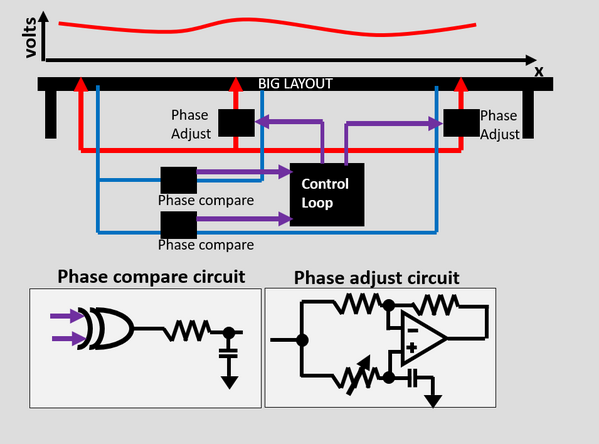
We don't really want to crank the legacy signal to max, or it starts to jam up the MTH-DCS signal also present on the same layout (see old post). So instead we do this approach where we feed the track and multiple points. The only catch is it's an RF carrier so if the length between the different feeds is wrong, the signal will actually be 90 to 270 degrees out of phase and start to cancel with itself instead of helping. To solve this we use 3 taps on the layout and two of the taps have phase adjustments so that each tap can be brought into phase.

To do the calibration we turn only one tap on first time and compare the track phase at the other two points where the other two feeds are to that first tap. We then adjust the other two feeds to match the phase we're reading back. This sequence is done by the little microcontroller on the board every 90 seconds... for a few milliseconds, so the trains don't even notice it's going on. The phase will drift with layout temperature, loading, number of trains.... so you do need to do it continuously

BOOSTER_GOOD

Not super complicated. You just need be aware combining RF signals has a 50% chance of diminishing them instead of increasing them if they are anti-phase or partially anti-phase. Then just pay attention to the details to straighten them out when you combine.

Honestly for 99% of signal problems GRJ's booster does a fine job on it's own. You only get into trouble if your layout has a really big aspect ratio (We're like 200 ft : 20 ft) and you have lots and lots of leakage to the ground (in our case from moisture since we're in a harbor). On top of this control loop we have a different control loop (in that linked post) that deals with the amplitude.

Attachments

Images (2)
  • BOOSTER_BAD
  • BOOSTER_GOOD
Last edited by Adrian!

Interesting, so if I remember my basic electric circuit stuff from well over 30 years ago, the controller you are using to fix the phase discrepancies is basically a phased lock loop (or am I off the wall with that? I have selective memory, weird what I remember..).  Pretty clever approach to the issue. I am fortunate/unfortunate, my layout is small enough won't have to deal with this.

Wow!  Adrian's passion for the electronics that run a layout is evident and the application of his skills is fantastic. I thank him for sharing what he has done.

This video really illustrates the draw of model railroading as it provides satisfaction for the hobbyist in unique ways. You find so many cool videos and posts by people on layout design, engine repair, landscaping, modeling, collecting, kit bashing, troubleshooting, railroad operations, railroad history, electronics et al. We're lucky to have a forum where you can discover tips from the best hobbyist out there. Even when I don't understand some of the things illustrated, it broadens my own knowledge and makes me curious to learn more.

Great Tour Adrian, I was amused about the TMCC phase adjustment where you said... "simple".  I'm sure many eyes were rolling when you said that!   I certainly see a lot of your fingerprints on all the control electronics there.

The DCS signal test rig was interesting, I think I could use that to single out problem locomotives.

Hey!

Rev2 and Rev3 diptrace files for the DCS tester are attached. If I remember right R3 uses the R2 board for a generator and R3 itself is just a more sensitive and more stable detector down at the other end of the track. The BIP supply in there is a little +/- buck module off amazon.  We've gone through so many versions of this... but the schematic should make it pretty clear whats going on. It's a crystal (pick a 3.5 MHz one) driving an ACT244 driving the test track. For the display I just went with these simple panel meters. They self-power down to about 3V which is fine since your fake DCS signal should be 5-15V range.

Attachments

Last edited by Adrian!
@Mannyrock posted:

     I'm sorry guys, . . . but it looks like a mess to me.   

     A good example of someone who likes wires and meters more than running trains.

    And, the reason there are so many of the "How many PhDs does it take to screw in a lightbulb?" jokes.   :-)

Mannyrock

all of these are in response to real technical problems that really happen really frequently in the large train club environment with junior members .

Before we tweaked the Lionel base most of our locomotives lost signal at one end of the layout or the other, stopped and caused pileups. Before we put the PSXACs in we were blowing up TIUs weekly. We melted down a good 7-8 locomotives on the subway before the timer went in. We had lots of problem trains with incandescent lighting that  interferes with robust control leading to runaway collisions that the test track sorted out.

When you have 9 members running 9 trains on one layout in 3 rooms these are all very real problems.

@Mannyrock posted:

     I'm sorry guys, . . . but it looks like a mess to me.   

     A good example of someone who likes wires and meters more than running trains.

    And, the reason there are so many of the "How many PhDs does it take to screw in a lightbulb?" jokes.   :-)

Mannyrock

As they say, in this hobby there are a lot of people in it, each with their own joys or whatever. GRJ enjoys running trains, but he also (I hope!) enjoys tinkering and applying his knowledge to making things work better/more fun.  To me when people write about things like this it is fun for me to read, to see how clever people are in applying knowledge to even something as "mundane" as a toy train layout (if that layout is mundane, I am elmer J fudd, Millionaire, with a mansion und a yacht).  I also enjoy clever work, which this seems to be, even though outside a very basic level it is way outside my wheelhouse.

I think what this really shows is with modern toy trains with the command control, it is kind of like how a character described the military in WWII, that it was a master plan designed by geniuses designed to be executed by more ordinary folk. To a user DCS and Legacy seem to be relatively simple, behind the scenes, not so much.

Adrian, thanks for sharing, really appreciate what you did to try and solve your problems, Mc Guyver would be proud

@bigkid posted:

As they say, in this hobby there are a lot of people in it, each with their own joys or whatever. GRJ enjoys running trains, but he also (I hope!) enjoys tinkering and applying his knowledge to making things work better/more fun.  To me when people write about things like this it is fun for me to read, to see how clever people are in applying knowledge to even something as "mundane" as a toy train layout (if that layout is mundane, I am elmer J fudd, Millionaire, with a mansion und a yacht).  I also enjoy clever work, which this seems to be, even though outside a very basic level it is way outside my wheelhouse.

I think what this really shows is with modern toy trains with the command control, it is kind of like how a character described the military in WWII, that it was a master plan designed by geniuses designed to be executed by more ordinary folk. To a user DCS and Legacy seem to be relatively simple, behind the scenes, not so much.

Adrian, thanks for sharing, really appreciate what you did to try and solve your problems, Mc Guyver would be proud

Thanks! When I joined the AGHR club it was like a demolition derby in terms of damaged layout equipment.


When you have a large membership it’s really hard to change habits especially when a good 30% are junior members. Even if you yell at everyone 10000 times to pay attention to their train (and I do), or to not stack heaps of incandescent passenger cars when other people are running, or to not leave the conventional stuff running unattended…. someone is still going to get distracted eventually and it’s nice that it doesn’t melt down hundreds of dollars of electronics anymore when that happens.

@Adrian! posted:

Thanks! When I joined the AGHR club it was like a demolition derby in terms of damaged layout equipment.


When you have a large membership it’s really hard to change habits especially when a good 30% are junior members. Even if you yell at everyone 10000 times to pay attention to their train (and I do), or to not stack heaps of incandescent passenger cars when other people are running, or to not leave the conventional stuff running unattended…. someone is still going to get distracted eventually and it’s nice that it doesn’t melt down hundreds of dollars of electronics anymore when that happens.

You know what is nice? That you have a large membership and that 30% are junior members. Having stuff melt down, not so much, but at least then there seems to be a future to the club. I'll have to watch the video again when I get a chance, to see if I understand fully what is going on.

@Adrian! posted:

Hey!

Rev2 and Rev3 diptrace files for the DCS tester are attached. If I remember right R3 uses the R2 board for a generator and R3 itself is just a more sensitive and more stable detector down at the other end of the track. The BIP supply in there is a little +/- buck module off amazon.  We've gone through so many versions of this... but the schematic should make it pretty clear whats going on. It's a crystal (pick a 3.5 MHz one) driving an ACT244 driving the test track. For the display I just went with these simple panel meters. They self-power down to about 3V which is fine since your fake DCS signal should be 5-15V range.

Thanks, one issue.  None of the discrete parts, resistors or caps, have any values.  Do you have a BOM that gives values?

Thanks, one issue.  None of the discrete parts, resistors or caps, have any values.  Do you have a BOM that gives values?

Hey...

So... I'm really lazy and usually draw the schematic first to set the topology, then calculate the values (filter time constants and gains) the circuit needs when I'm actually populating the board (since there's always tweaking of values at runtime). The values on these boards are:

Rev 3
-----------
R1 500-1K
R2 5000
C2,C3,C4,C5 0.1uF
R6 100-200 ohm
D2,D3 1n4148
C7,C8 0.1uF
R7,R3 10K
R9 8-10K
R8 8-10K
C9 0.1uF
C10 0.1uF
R10 8-10K trim

Rev 2
--------
R1 1K
C5,C6 0.1uF
R4,R5 10K trim
INV  74HCT04
DRV  ACT844
REG  7805

@rtr12 posted:

Great tour of the club layout controls for preventing equipment damage!  I really enjoyed it, along with all the things you have come up with the solve the club's problems.  Fascinating stuff, thanks for posting and sharing it all here.

I love solving train-electronics problems, if yourself or anyone else here has a unique train electronics problem, I'm always down to see if I can figure something out for you! I don't even charge money.

It's like free design engineering!

Great job, Adrian. Thank you for all of your efforts to make the AGHR layout operate reliably under multiple control systems.

I can tell you from personal experience that the AGHR layout has evolved from a conventional-only layout back in 1995 to essentially command-only about ten years ago. The big problem was that there are things you do to get a conventional layout to work reliably that are about the worst thing possible for packet-based command transmission.

The original TMCC command system was easy as it was designed to just attach to a conventional layout. However, when we got DCS (we got ours before the dealers in California got theirs thanks to our dealer, Sean Marchev who picked them up from MTH when the air-shipped sets came in and FedEx shipped them to us) we found out that buss wiring was your worst enemy and had worked for years to clean it up. Adrian's analysis of the signals going into the layout was invaluable in cleaning out interference issues on the layout.

Hopefully, since my home layout will only be about the size of the staging area, my wiring will have fewer TMCC/DCS issues, but I'm going to be adding a wrinkle of adding a switch-over to operate it under DCC. What I'm analyzing is the best location to place the main junction that will feed the different systems into the layout buss.

OK Ill bite, Where does one get those cool looking oscilloscopes ? Would the oscilloscopes work in a conventional set up after power from transformer?

Hey there, so the conventional voltages after the transformer should work fine as long as you don't go over say 30V. Even if you do, you can solve that with a resistor divider (basically put like a 10K and 100K resistor in series) and tap the middle to the oscilloscope. If you need a doodle let me know and I'll draw it up for you.

These are the oscillscopes we use. We have 20 of them I think? (5 TIU x 4 ports) in our layout.

@60-66 posted:

Thanks for sharing, lots of knowledge, helpful to me.

Went back and viewed a couple of times, and saved.

Also, thank you for your work work, keeping America great.

Les

I'm glad to answer any questions, and chances are if there's something specific you're interested in I can point you to a prior post here on the OGR forum with all the details.

Last edited by Adrian!

First time I ever saw these in a practical installation.  A few years ago I actually bought one of these to tinker with, but I'll stick with my Rigol 'scope.

Given the low bandwidth, how well does it do with the DCS signal?

The DCS is like 3.2 MHz and the scope is only 1MS/s, so you're only getting like 1 waveform sample every 3 bit times. It's definitely not good enough to see what the DCS packet is saying or how crisp the digital waveform is (you still need a big-kid scope for that), but it's really really useful to just make sure the packet amplitude is about right.

When I turn a train on, I'm always glancing at these to make sure I see packets going the train-TIU way, then packets going the TIU-train way, and that those packets are you know... 10-14V tall. Also if you can't find a DCS engine on the remote app it's a really easy way to just glance over and see is there activity?, and is it one way or both ways?  It's a bit costy to put 20 of these, but it is a lot more convenient then getting the real scope out all the time.

@Adrian! posted:

I love solving train-electronics problems, if yourself or anyone else here has a unique train electronics problem, I'm always down to see if I can figure something out for you! I don't even charge money.

It's like free design engineering!

OK I need help... I have one loop of track 300' long, divided into four blocks, each powered a single Lionel 180 brick, going through a single TIU using four channels.  I run multiple trains, some with engines front and rear. I need a system that when one block trips the breaker on all four blocks trip, One heck of a derailment if they all don't trip.


Clem  

@clem k posted:

OK I need help... I have one loop of track 300' long, divided into four blocks, each powered a single Lionel 180 brick, going through a single TIU using four channels.  I run multiple trains, some with engines front and rear. I need a system that when one block trips the breaker on all four blocks trip, One heck of a derailment if they all don't trip.

Probably best addressed in a new thread, but…

There are lots of ganged breakers out there that will do this sort of thing.  The breakers that protect 240v appliances in your home are set up this way.  There might be 4 pole versions out there as well.  Another way would be to use shunt and/or voltage trip breakers.

@clem k posted:

OK I need help... I have one loop of track 300' long, divided into four blocks, each powered a single Lionel 180 brick, going through a single TIU using four channels.  I run multiple trains, some with engines front and rear. I need a system that when one block trips the breaker on all four blocks trip, One heck of a derailment if they all don't trip.


Clem  

And AND gate and a relay would be my first thought but I bet someone sells something for this already. I see others have suggestions too. If none of those work for you let me know and I can doodle something up for you.

@TheRambles posted:

This is one of the coolest things I've seen on the OGR forum in a long time!

@Mannyrock posted:

     I'm sorry guys, . . . but it looks like a mess to me.   

     A good example of someone who likes wires and meters more than running trains.

    And, the reason there are so many of the "How many PhDs does it take to screw in a lightbulb?" jokes.   :-)

Mannyrock

These two sets of comments, coming from wildly opposite, but each quite valid, perspectives, convey the present breadth and depth of our hobby.

Does anyone see a problem here?

      What ever happened to K.I.S.S.?

A number of times I've attempted to coach @Mannyrock and others like him, trying to bring encouragement that things are always less complex than they seem, that the hobby's about learning and that tinkering is a big part of it, that the products we buy are generally solid but may not be bulletproof, and that many of us forumites are here to help folks turn small steps forward into big ones.  Thank goodness that he, and they, have been patient with us.

But, from this video the sheer number of big problems that the AGHR folks have encountered, characterized, and solved is nothing less that a show-stopper for the average Joe.

Talk about intimidation.

How did things get this to this point?  Is it just because the AGHR layout is so big?

I applaud @Adrian! and his fellow club members for digging in and solving these vexing problems.

Don't get me wrong.  Like many of us I learned the very first technical things I encountered at, 6, 7 or 8 years old, by playing with my Lionel 1513S set.  I have deep respect for the learning process that comes out of using your hands and the right tools (starting with toys) to make amazing things happen.  As I approach retirement within the next few years, I'm deeply thankful for what our hobby has taught me -- what I have used every day of my work life as an electrical engineer, for over 45 years.

I don't like saying this but from what we see in the video it seems to me that the folks who designed TMCC/Legacy and DCS didn't think them through deeply enough before putting them into the field.

Even more troubling is the fact that they evidently didn't embrace K.I.S.S.

Why else would so many big, but in the end solvable, problems present themselves?

This is a double-edged sword.  Giving the hobbyist a way to build on little things in order to solve big problems is good.  This is a large part of what we now call S.T.E.M.  At the same time what about those that get left behind?

Let's take a look back over the last 25 years, over the "command control" era.  Investing significant time and money, even if it's free, to fix expensive things that should not be broken if they were designed properly in the first place, may not be not conducive to the future health of the hobby.

What do you think?

Mike

I looked for years now, a friend of mine made up a board (plywood) for me that had 12 relays and four toggle switches mounted on it, It worked very well but as since given up and smelled like smoke. so I took it out.  I tried the electrical supply houses but they don't deal with low voltage stuff. Someone sent me photos of the relays he uses, suppose to run a rod through all the levers so that they all trip. However they are only 2 amps each. If I could find something like that with 10 amps that would probably work. Ordering on line only works if you know what you exactly want.

@clem k thinking about this issue a while, I think @Adrian! 's suggestion may be the simplest and still keep the benefits of the fast electronic breakers in the PH-180.

A 4 input AND Gate controlling 4 relays could be connected so that all 4 relays would interrupt the current flowing from all 4 PH-180' outputs simultaneously, if any of the breakers tripped.  If you're unfamiliar with logic gates, the way they work is they provide a control voltage on their output that can be used to trigger a relay or other logical device.  AND gates will only turn on their output voltage (high) when all of their inputs are triggered on (high).  The AND gate would only keep the relay closed (passing track current) if all four of it's inputs are high (PH-180's not tripped).

Last edited by SteveH
@clem k posted:

Thanks Steve, really appreciate the information but I have no idea what you just said  I never heard the term gate with electricity. Maybe that is what my friend made for me, looks like three relays per block.

One thing to note is the PH180 breakers are super fast but a regular relay is not (if you look at this on millisecond timescales of the fault). That’s why you probably want an electronic solution not an electromechanical one. You want to keep the reaction time fast so nothing gets cooked.

Clem, logic gates are electronic devices that work similarly as a bunch of small interconnected relays, only with less current carrying ability and less expense. But, they can control larger relays than can handle the 10 amps that the PH180's output.

For this application the gates would be packaged in a small microchip, probably with about 8 or so pins.   Logic gates are essentially what a computer uses to run code, just on a much bigger scale.

If you're interested in reading more about logic gates, here's a link to more information: https://en.wikipedia.org/wiki/Logic_gate

For your application, the connections and logic involved would be minimal, not nearly as sophisticated as a modern computer microprocessor.

Add Reply

Post

OGR Publishing, Inc., 1310 Eastside Centre Ct, Suite 6, Mountain Home, AR 72653
800-980-OGRR (6477)
www.ogaugerr.com

×
×
×
×
Link copied to your clipboard.
×
×