Hi Again!


===========ABSTRACT===========

I think that it's pretty common knowledge that if DCS isn't optimal that the add engine command tends to struggle more than the simpler ones (whistles, speed commands and such). I figure some folks might already have the deep understanding into this, but I wanted to put it up in detail because several people asked me to, most recently rad400 on the other post.


========== SNR and BER ========== 

To start this discussion we need a bit of communication theory, but not too much and I'll try to keep it sort of qualitative and skip the mathematics. The most basic quantity in communications is called signal-to-noise ratio or "SNR". Noise is complicated to talk about, there are many types: noise from power supplies (called line noise), noise from digital circuits nearby (called switching noise), noise from the transistors in the circuits themselves (called thermal, flicker, shot, and Nyquist-Johnson noise), and noise from something like a model train that runs down the track and makes and breaks connection (called point noise). You don't need to know exactly how much of what type of noise you have to analyze a communication system, just the total amount of unwanted noise power compared to the power of signal you are sending. In many cases signals from unrelated systems are even considered noise (like TMCC to a DCS system is considered a noise because its energy in the system that doesn't help send a DCS signal).

So SNR is essentially (signal energy you want) divided by (any noise or signals you don't want).  For trains you can think of it like the "strength" of the DCS signal telling your train what to do divided by the "strength" of *any* other signals on the track.

The second concept we need to borrow is Bit Error Rate (BER for short). Bit error rate describes how often a bit is sent wrong (like I sent a 1 to the train but it got a 0). There is a direct relationship between the SNR and the BER. The lower the SNR, the higher the BER.

If you have a weaker signal, more bits will be wrong. This is fundamental to all communication systems (cell phones, wifi, space missions, trains...whatever). Depending on exactly how you encode the data and modulate, the exact coefficients of the relationship change, but the general story is always the same: BER goes up when SNR goes down.  This is often represented with a SNR to BER plot which does the conversion for a given type of communication.

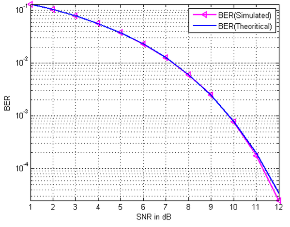
DCS uses a type of encoding called CDMA (Code-Division Multiple Access) with a modulation called bi-phase line code (meaning it has both + and - voltage in the waveform). The SNR-BER relation for CDMA-biphase looks like this:

SNR_BER

SNR is usually expressed in dB which is 20*log10([volts signal]/[volts noise]). So 6dB is a factor of 2 in voltage, 12 dB is a factor of 4 and 20 dB is a factor of 10. So for example if you look at the plot, you can see an SNR of 6dB (meaning the signal voltage is 2X higher than the noise voltages) gives you a BER of 9x10^-1 or roughly 0.09. What this is saying is

If the noise voltage is half the signal voltage then of every 100 bits I send, 9 will be screwed up.  Similarly at 12dB (a factor of 4) the BER is almost 10^-5 meaning for every 10000 bits I send, approximately 1 will be screwed up.

So the take away is a weaker signal or a stronger noise/interference (a lower SNR) means a higher chance that bits will be screwed up.


==========How command length and BER relate ========== 

All the DCS signals are sent with the same strength because they all come from the same transmitter circuit. No commands are weaker and no commands are stronger. The only difference is the length of them (the number of bits inside).

So for example (it's not really these numbers) lets say the add engine command is 12 bits long while the whistle is only 3 bits long, and we have a BER of 0.1 (meaning 10% of bits are sent wrong). That means the chances of sending an individual bit correctly is 90%

This means the chances of sending our whistle command (3 bits) correctly is

(90%) X (90%) X (90%) = 73%. So we have a pretty good chance of getting it right most of the time.

Now our add engine command is

(90%) X (90%) X(90%) X (90%) X(90%) X (90%) X(90%) X (90%) X(90%) X (90%)X(90%) X (90%)   = 28%

So it basically only works about 1/3 of the time.

This is the core reason why the add engine command is more sensitive. It is longer than other commands so the chances of sending it successfully are lower.

=====Repeating the command======

DCS is not stupid and knows when a command is broken or not received, so it will keep trying to send the same command over and over until it works. From our simple example we have a 28% chance of adding an engine successfully, so on average 1 out of 4 times will work. If you flip this around.... that means to make it work correctly, on average the TIU will have to send our add engine command 4 times.  This is why in good conditions you can add a train very quickly, while in bad conditions it may take a very long time. If the DCS system tries to send the same command and fails more than 100 times it just gives up and tells you "engine not on track" or "RF out of range".

==========Okay to real DCS numbers and measurements========== 

Of course if a communication link screwed up 10% of the data it would go to the trash bin. Real DCS is designed to operate at error rates of 1 in 100,000 (BER 10^-5) to 1 in 10 million (BER 10^-7). The real thing to know is how different the length of different commands are.

Here is a direct comparison of the real DCS command for add-engine (my DDA40x on the track) and to blow the whistle.

add_dcs_command

The whistle command is hard to see so here is a zoom in of one of the exchanges:

whistle_command


Lets do some basic calculations.

--> DCS runs at roughly 3MHz (It's really more like 3.25 MHz), meaning it sends about 3 bits per microsecond.

--> Each part of the whistle command is about 400us long, meaning it contains about 1200 bits of command data times 2 (for the two parts). That's 2400 bits total per whistle blow.

--> The add engine is 1.7 seconds long or 1,700,000 microseconds. There are idle gaps and it's active somewhere around 30% of the time (similar to the whistle command). So the number of bits is somewhere in the neighborhood of 1,700,000 X 3 bits/us X 30% which is 1,700,000 bits.

Right so lets say we had a fairly reasonable bit error rate of 1 in a million. So 1 out of every million bits sent would be wrong. That means the probability of the whistle working is

(999,999/1,000,000)^2400 = 99.9988% chance of being received in 1 try.

Now the command signal for add engine:

(999,999/1,000,000)^1,700,000 = 18%.

So on average the add engine command will need to repeat about 5 times (18% X 5 is about 100%) to ensure it is exchanged successfully.


=====Practical measurements with a DCS system======

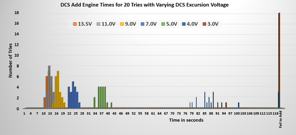
So as an experiment I had an attenuator (device that reduces signal voltage) connected between my TIU and test track and slowly dialed down the DCS excursion voltage to 13.5V, 11V, 9.0V, 7.0V, 5.0V, 4.0V and 3.0V. In each case the noise was the same so the SNR is going down with each step. At each voltage setting I tried the add engine command 20 times (yes! that's 140 times and it took all day) and wrote down how long it took, or if it failed to add altogether.

Here is the resulting histogram:

command_test

With a nominal DCS voltage (13V) you can get add times in the 10 second range. At 7.0V you are starting to see delays into the 20 second regime. At 5.0V you're up in the 30-40 second range, and below that you start to see a lot of failures. Note the 3.0V condition failed to transmit the command 18 out of 20 times.

If you look at the figure "SNR vs BER" up at the top, it has an exponential relationship. The DCS add engine delay is also exponential (the difference between 13V and 11V is smaller than the difference between 11V and 9V which is smaller than the difference between 9V and 7V and so on. This exponential behavior shows the underlying BER/SNR behavior of the long add-engine command.


=====Take Away======

The longer length (in bits) of the add engine command compared to other commands makes it more prone to errors (and needing repeated transmission) in the DCS system:

Whistle: ~2400 bits

Add Engine: ~1,700,000 bits


The time it takes to add engines is set by how many times the system must retry the command before it is successful which is set by the underlying bit error rate, which in turn is set by the system signal-to-noise ratio.

Note: These are statistical measures so you need to retry them a number of times (20 in the above case) to characterize them, as you will always have statistically unlikely exchanges (sometimes a statistically lucky packet may have no errors and add fast).

Attachments

Images (4)
  • SNR_BER
  • add_dcs_command
  • whistle_command
  • command_test
Last edited by Adrian!
Original Post

Replies sorted oldest to newest

One other thing I forgot to transfer from my notes to the post: The whistle and other commands are very short (100s to 1000s of us) so when they are repeated over and over (say 10 times instead of 1 time) it's not perceivable to the user. The add engine is 1.7 seconds long, so repeating it over and over is very perceivable.

David Minarik posted:
gunrunnerjohn posted:

Dave the voltage being discussed is the DCS carrier, not the track AC voltage.

John,

Is it not the same?  Can you explain?

Thanks!

Dave

Hi There!

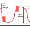
Here's a doodle I made for someone else yesterday. Now it's for you too!

voltage

The track has a 60 Hz voltage to power the trains (usually like 10-25V depending on what power source and such). It also has super-imposed on top of that the digital signal for DCS. We are talking about measuring this digital voltage, not track voltage. The digital packets are infrequent and at a high frequency which is why you need to filter them with to measure them independently of track power.  It's this DCS digital voltage (formal name is excursion voltage) that limits your DCS link quality and that is being discussed here.

Attachments

Images (1)
  • voltage
Last edited by Adrian!

The ultimately noisy communication environment is something we call "the real world". Whether the world is real or not is (actually) open to debate. But digital communication between sender and receiver in our world is fabulously well-researched and documented. Ham radio operators are now using digital modes that are so successful that world-wide communication is routinely achieved in environments where noise is, by all tests and measures, overwhelming. 

Many of these digital communication modes are open-source--free for non commercial use. I suggest that MTH license one of them for use in DCS. Here is a great source for such a license: https://physics.princeton.edu/pulsar/k1jt/ Not only would they fix their weak signal performance in DCS, they would be supporting some very worthwhile research.

Don Merz


Adrian! posted:
David Minarik posted:

Adrian/John,

Does the DCS packet ride on a portion of the track voltage wave?

Sorry for the amateur questions.  Thank you for taking the time to explain.

Dave  

Exactly right!

Does increasing the track voltage have ANY affect on the DCS signal or the portion of the wave that the signal rides on?


David Minarik posted:
Adrian! posted:
David Minarik posted:

Adrian/John,

Does the DCS packet ride on a portion of the track voltage wave?

Sorry for the amateur questions.  Thank you for taking the time to explain.

Dave  

Exactly right!

Does increasing the track voltage have ANY affect on the DCS signal or the portion of the wave that the signal rides on?


My guess is that operating at voltage lower than 12 volts could affect this. Operating at voltages that low isn't recommended anyway. But I'll defer to the expert on this.

Another question, does operating on DC vs. AC power improve communication quality?

H1000 posted:

My guess is that operating at voltage lower than 12 volts could affect this. Operating at voltages that low isn't recommended anyway. But I'll defer to the expert on this.

Another question, does operating on DC vs. AC power improve communication quality?

The voltage for the dcs doesn’t come from track power so they shouldn’t affect each other. The AC power sine wave is 60Hz so if you think about what that looks like on the scale of microseconds.... it’s basically already a straight line. So in a way it feels like DC already to the DCS signals.


FWIW, when you're loading sound files and chain files, using DC does increase the reliability, so there is a difference.  Nowadays, on my bench, I normally do my loading with DC to the TIU, and I get faster loads and no dropping back to lower speeds because of errors in transfer.  Others have also commented on more reliable sound file loads using DC to power the TIU and locomotive.

Adrian! posted:
H1000 posted:

My guess is that operating at voltage lower than 12 volts could affect this. Operating at voltages that low isn't recommended anyway. But I'll defer to the expert on this.

Another question, does operating on DC vs. AC power improve communication quality?

The voltage for the dcs doesn’t come from track power so they shouldn’t affect each other. The AC power sine wave is 60Hz so if you think about what that looks like on the scale of microseconds.... it’s basically already a straight line. So in a way it feels like DC already to the DCS signals.


Where is it generated?  There is no transformer in a TIU.   I think I am really missing something here.  

Again thank you your patience!

Dave

gunrunnerjohn posted:

FWIW, when you're loading sound files and chain files, using DC does increase the reliability, so there is a difference.  Nowadays, on my bench, I normally do my loading with DC to the TIU, and I get faster loads and no dropping back to lower speeds because of errors in transfer.  Others have also commented on more reliable sound file loads using DC to power the TIU and locomotive.

John, is there anything special with your bench setup? I tested all sorts of different methods when downloading (realizing that this process should take longer than uploading) a file from an engine but AC vs DC didn't seem to make much difference. The biggest improvements were seen when I went from a Rev. G to a Rev. L TIU and downloading from PS3 vs a PS2 (3 volt) engine.

I've also heard that using a long set of wire between the test track and the TIU will also help. I tried this with a 15 foot bonded 16 gauge wire set which didn't seem to make a difference.

Just curious what your ideal setup looks like, Thanks!

gunrunnerjohn posted:

The AC track voltage is coming in the input of the TIU channel.  If you're running passive mode, it's coming in the output side.  The AC if obviously supplied by an external transformer.

John,

See the quotes in my reply.  Adrian said "The voltage for the dcs doesn’t come from track power"

Thanks,

Dave

I thought you were talking about the 60hz.  The DCS signal is generated internally by the TIU electronics.  It can receive power from FIXED #1 or the AUX Power inputs of the TIU.  Either will power the TIU logic board and DCS signal generators.  However, you must have power on the TIU channel in question in order to get the channel to output the DCS signal, so you really do need a transformer connected to the channel you're testing.

Last edited by gunrunnerjohn
gunrunnerjohn posted:

FWIW, when you're loading sound files and chain files, using DC does increase the reliability, so there is a difference.  Nowadays, on my bench, I normally do my loading with DC to the TIU, and I get faster loads and no dropping back to lower speeds because of errors in transfer.  Others have also commented on more reliable sound file loads using DC to power the TIU and locomotive.

John, how is there a difference in outcome between AC and DC input to the TIU ( regardless of whether it is fed in through the posts or aux input)? Doesn't the TIU convert AC to DC internally either way (hopefully with capacitor smoothing)?

Last edited by GregR

The TIU has a rectifier and a lm7805 +5V regulator inside meaning regardless of what voltage is presented to it, it will always run the transmitter drivers at 5V differentially. So the dcs power does come track power, but the dcs voltage is totally independent of the input track voltage because of the regulation behavior. There is capacitive smoothing, after the rectifier but before the regulator.


the 60Hz affecting behavior is interesting to me. I will look into/think about it and try to get you an explaination


Could that be one reason why later MTH engines have a "SXS" one button push for a crossing signal sound in place of the four individual button pushes formerly used (for two longs, one short, and one long)?  (I thought it might have been to extend the DCS handheld battery life since there is no need to keep the button depressed for the "long" sounds...!)

Adrian! posted:

The TIU has a rectifier and a lm7805 +5V regulator inside meaning regardless of what voltage is presented to it, it will always run the transmitter drivers at 5V differentially. So the dcs power does come track power, but the dcs voltage is totally independent of the input track voltage because of the regulation behavior. There is capacitive smoothing, after the rectifier but before the regulator.


the 60Hz affecting behavior is interesting to me. I will look into/think about it and try to get you an explaination


That answers the question!  Thank you!

Hudson5432 posted:

Could that be one reason why later MTH engines have a "SXS" one button push for a crossing signal sound in place of the four individual button pushes formerly used (for two longs, one short, and one long)?  (I thought it might have been to extend the DCS handheld battery life since there is no need to keep the button depressed for the "long" sounds...!)

The "SXS" is a specific sound that is recorded into the sound file. It is not a "macro" of predetermined key presses of the horn button. If you listen carefully many of the engines with the SXS function have a slightly different tone and pitch than the regular horn.

Don Merz 070317 posted:

The ultimately noisy communication environment is something we call "the real world". Whether the world is real or not is (actually) open to debate. But digital communication between sender and receiver in our world is fabulously well-researched and documented. Ham radio operators are now using digital modes that are so successful that world-wide communication is routinely achieved in environments where noise is, by all tests and measures, overwhelming. 

Many of these digital communication modes are open-source--free for non commercial use. I suggest that MTH license one of them for use in DCS. Here is a great source for such a license: https://physics.princeton.edu/pulsar/k1jt/ Not only would they fix their weak signal performance in DCS, they would be supporting some very worthwhile research.

Don Merz


if this is possible it would solve our clubs issues.

can we try this? 

bigdodgetrain posted:
Don Merz 070317 posted:

The ultimately noisy communication environment is something we call "the real world". Whether the world is real or not is (actually) open to debate. But digital communication between sender and receiver in our world is fabulously well-researched and documented. Ham radio operators are now using digital modes that are so successful that world-wide communication is routinely achieved in environments where noise is, by all tests and measures, overwhelming. 

Many of these digital communication modes are open-source--free for non commercial use. I suggest that MTH license one of them for use in DCS. Here is a great source for such a license: https://physics.princeton.edu/pulsar/k1jt/ Not only would they fix their weak signal performance in DCS, they would be supporting some very worthwhile research.

Don Merz


if this is possible it would solve our clubs issues.

can we try this? 

does anyone know if this is feasible? or doable?

Hey! Changing encoding protocols would basically be like a complete re-design of DCS from scratch. The PS boards in the engines, the TIU board, the firmware, all of it would need to be redone. I mean it'd be a fun project if you had the time. Also you'd have to do it to all the trains that run in the club. Sounds hard!

At the club we have been having some issues with the "add engine" command when the TIU is integrated into the layout.

After reading several of Adrain's posts, I tried out a new TIU which I first used on a test track, separate from the layout.  I was able to successfully use the  “add engine" command and also many of the other commands using the MTH handheld without any problems up to ~ 70' from the TIU. Then I upgraded the TIU with the antenna listed in one of the earlier posts and again had no issues with the "add Engine" command.

Next I installed the new TIU with the upgraded antenna in the layout, made sure that all the channels were on, fixed & super TIU mode were on.  I was standing 4 feet from the TIU and tried the “add engine" command, and I got the notorious "engine not on track" or "RF out of range" message.  All the other commands worked fine and TMCC was turned off for this testing.

Then I tried using the DCS app and I also tethered the handheld to the TIU.  In both cases, I was successful with the “add engine" command.  So I seems my TIU-Track-Engine communication path is OK.

Is there something I can test to see where the "add engine" communication link is breaking down when the TIU is part of the layout?

Thanks,
Bob D 
nj-hi railers
Adrian! posted:
bigdodgetrain posted:
Don Merz 070317 posted:

The ultimately noisy communication environment is something we call "the real world". Whether the world is real or not is (actually) open to debate. But digital communication between sender and receiver in our world is fabulously well-researched and documented. Ham radio operators are now using digital modes that are so successful that world-wide communication is routinely achieved in environments where noise is, by all tests and measures, overwhelming. 

Many of these digital communication modes are open-source--free for non commercial use. I suggest that MTH license one of them for use in DCS. Here is a great source for such a license: https://physics.princeton.edu/pulsar/k1jt/ Not only would they fix their weak signal performance in DCS, they would be supporting some very worthwhile research.

Don Merz


if this is possible it would solve our clubs issues.

can we try this? 

does anyone know if this is feasible? or doable?

Hey! Changing encoding protocols would basically be like a complete re-design of DCS from scratch. The PS boards in the engines, the TIU board, the firmware, all of it would need to be redone. I mean it'd be a fun project if you had the time. Also you'd have to do it to all the trains that run in the club. Sounds hard!

so there is no way to increase the tiu signal output?

that is what I read don merz post

rad400 posted:

At the club we have been having some issues with the "add engine" command when the TIU is integrated into the layout.

After reading several of Adrain's posts, I tried out a new TIU which I first used on a test track, separate from the layout.  I was able to successfully use the  “add engine" command and also many of the other commands using the MTH handheld without any problems up to ~ 70' from the TIU. Then I upgraded the TIU with the antenna listed in one of the earlier posts and again had no issues with the "add Engine" command.

Next I installed the new TIU with the upgraded antenna in the layout, made sure that all the channels were on, fixed & super TIU mode were on.  I was standing 4 feet from the TIU and tried the “add engine" command, and I got the notorious "engine not on track" or "RF out of range" message.  All the other commands worked fine and TMCC was turned off for this testing.

Then I tried using the DCS app and I also tethered the handheld to the TIU.  In both cases, I was successful with the “add engine" command.  So I seems my TIU-Track-Engine communication path is OK.

Is there something I can test to see where the "add engine" communication link is breaking down when the TIU is part of the layout?

Thanks,
Bob D 
nj-hi railers

You can try the tether to make sure the Train-Track-TIU section is okay, then the short test track on the same channel output to make sure the Remote-TIU is okay.

bigdodgetrain posted:

so there is no way to increase the tiu signal output?

that is what I read don merz post

He's talking about using a different base encoder, some open standards that perform better than the existing "DS/SS 31/27" code MTH uses. The code originates in the FPGA on the PS board and TIU board.

If you got your hands on the RTL code you possibly might be able to change it. I think some of the hardware (transformers, drivers and such) would have to change since the bandwidth and code statistics would be different.

Adrian! posted:
rad400 posted:

At the club we have been having some issues with the "add engine" command when the TIU is integrated into the layout.

After reading several of Adrain's posts, I tried out a new TIU which I first used on a test track, separate from the layout.  I was able to successfully use the  “add engine" command and also many of the other commands using the MTH handheld without any problems up to ~ 70' from the TIU. Then I upgraded the TIU with the antenna listed in one of the earlier posts and again had no issues with the "add Engine" command.

Next I installed the new TIU with the upgraded antenna in the layout, made sure that all the channels were on, fixed & super TIU mode were on.  I was standing 4 feet from the TIU and tried the “add engine" command, and I got the notorious "engine not on track" or "RF out of range" message.  All the other commands worked fine and TMCC was turned off for this testing.

Then I tried using the DCS app and I also tethered the handheld to the TIU.  In both cases, I was successful with the “add engine" command.  So I seems my TIU-Track-Engine communication path is OK.

Is there something I can test to see where the "add engine" communication link is breaking down when the TIU is part of the layout?

Thanks,
Bob D 
nj-hi railers

You can try the tether to make sure the Train-Track-TIU section is okay, then the short test track on the same channel output to make sure the Remote-TIU is okay.

I tethered the handheld-TIU when I was connected to the layout and used a short test track when I was initially testing the TIU and everything was fine.

Adrian! posted:
bigdodgetrain posted:

so there is no way to increase the tiu signal output?

that is what I read don merz post

He's talking about using a different base encoder, some open standards that perform better than the existing "DS/SS 31/27" code MTH uses. The code originates in the FPGA on the PS board and TIU board.

If you got your hands on the RTL code you possibly might be able to change it. I think some of the hardware (transformers, drivers and such) would have to change since the bandwidth and code statistics would be different.

got it.


doesn't hurt to ask!

Add Reply

Post
The DCS Forum is sponsored by

OGR Publishing, Inc., 1310 Eastside Centre Ct, Suite 6, Mountain Home, AR 72653
800-980-OGRR (6477)
www.ogaugerr.com

×
×
×
×
Link copied to your clipboard.
×
×