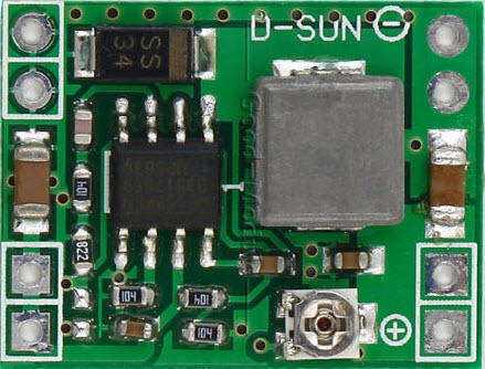
I've been batting this idea around for some time, and decided I'd take a stab at making my own variable AC-DC power supply that included stuff like DCS compatibility, as well as common ground capability for compatibility with TMCC systems.  I frequently want an independent source of power in projects, this seems to be a good way to solve that problem.  Here's the result of my thinking, it's simple and to the point.  I use one of the many Chinese small switching modules as my switching power supply base and just add the DCS choke, input rectification, and filtering for the switching module.  I did an initial design with one large capacitor and the DC-DC module on top, but that ended up making the board larger than it needed to be with wasted space.  I get the same amount of filter capacitance with two smaller capacitors, and the whole board sandwich ends up being quite a bit smaller.  Having the smaller capacitors allowed me to put the DC-DC module under the main board and still have access to the voltage control pot.

In testing the DC-DC module, I discovered that under load the component that gets the hottest is the small ferrite encased coil.  Conveniently, it's also the tallest part on the board.  In an effort to provide a bit more thermal heat dissipation, I use a copper pour on the board that will sit on top of the module to spread the heat.  The module will be bonded to the bottom of the board with thermal adhesive to promote heat transfer.  The top PCB has connections that match the connections on the DC-DC switching module, jumpers will go between the two boards to connect them and to provide structural support.  A hole is provided in the upper board to allow access to the voltage adjustment pot of the DC-DC switching module.

Here's a schematic and the PCB layout of the board, placed an order for prototypes, it'll be interesting to see how this works out.  I should be good for several hundred milliamps of current, I haven't tried to push it to see how much I could get out of it.


AC-DC Power Module Documentation

Attachments

Images (1)
  • AC-DC Power Module Documentation
Original Post

Replies sorted oldest to newest

Yep, I realize that.  As long as I stay at 18-19 volts AC input, I am running less than 23 volts on it open circuit and less under load.  I picked it because of the small size, I wanted something that would result in the smallest module possible.

The reason for not using the bridge is I want a common ground for many of my applications, so if I use a bridge, I lose that capability.

The dimensions are.

21.35mm (.841") x 12.25mm (.482") are the base board dimensions.  The switching module is a bit smaller.  The board stack will be about 18mm (.75") high considering both boards.

When I get the blank boards in, I'll build a couple up and post completed pictures. of the unit.  At that point, I'll do some power tests to see what the limitations are.

I understand the common-ground application for TMCC and such.  But I'll bet there are an equal number of applications to use something like this with ANY of the various step-down, step-up, step-down/up, LM2596, etc. modules.  In other words, DCS filter, AC-to-DC, and some amount of bulk capacitance.  So now I'm imagining how easy it would be for you to modify (or make a variant) the board that takes a bridge (maybe 1/2A MB10 foot-print like you use on the Hennings module) in place of a single-diode.  Perhaps easier to fab a different board, but in the case of LM2596 modules which have a 100uF or 220uF input caps, you could eliminate one (or both) of the 150uF caps and use the real-estate to drop in a bridge.  Same PCB but selective population: either install 1 diode, 2 caps...or a bridge rectifier and 0/1 cap.

Also, what did you baseline for the power-handling capability of the 22uH? 


Stan, I know I could make a different form factor with different capabilities, even I can imagine that.   I was targeting a specific requirement I have for upgrades of TMCC stuff for a DC supply from track power.  I also wanted the total package to be as small as possible, that's why I picked the really small switcher.  This really isn't destined to become something I'd mass produce as by the time I made any profit on it, it would be priced out of a reasonable range.  The 22uh choke is rated at 3/4 A, more than I expect I can realistically get out of the tiny switcher board, and since that's input current, it'll typically be much less than the output current.

The board fab for my prototype quantity of 41 boards was $36 shipped, it's not a huge burden to lay out another one if I wanted to expand the capability.

We discussed this before, and I figure that for most of the things I'd want to use this supply for will be covered by this design.  If I really wanted to do a more complete model, I'd probably bite the bullet and lay out the switcher parts as well on a single board.


All understood.

The general "problem" is there are so many incredibly priced eBay modules that just need 3 or 4 components to make them work with our wacky O-gauge AC track voltages.  Usually it's a DCS 22uH inductor, a diode or bridge-rectifier, a capacitor, a resistor or two, etc.  $1 or less in components, but what a nuisance to gather the parts, solder/assemble etc..  And really a nuisance if trying to use the surface-mount versions of the components which is generally preferred to better fit in rolling stock and such.

A classic is the relay for isolated-rail triggering of signals or accessories.  The eBay 12V DC relay module is a ridiculous $1 shipped.  But as you well know since you've posted the circuit dozens of times (!) you need a diode for AC-to-DC, a capacitor for anti-chatter, a resistor or two to limit current, and the DCS inductor if using track voltage.  If only there was a low-cost board whether a DIY bare-board or assembled.  Well, I shall continue to imagine someone else doing this! 


Last edited by stan2004
stan2004 posted:

All understood.

It is a shame that there isn't a truly cost-effective way to have stuff produced in modest quantities, I have all sorts of cool ideas if production costs were reasonable.  

Occasionally, I hit on something like the lighting module or the Super-Chuffer that can be produced in sufficient numbers to make it cost-effective, but stuff like this power module seem to be much more marginal.  The fact that I'd have to commit to a quantity, and pay the up-front tooling charges, makes the idea much less attractive.  Like I said, if I were going to make one for sale, I'd have to seriously consider laying out the switcher components as well to optimize the design.

I had a brand new Lionel trackmbile that I put on the track to let the grandson run. He turned up the handle on the Z4000 slowly and it ran good. It then stopped and nothing. No smoke or blink or anything. I have to believe the handle went just a hair too high and something went. It was not going all that fast. I don't see any burnt components inside either? Probably went a hair over 18 volts a quit?

Stan, here's an alternative you might like.   I took a stab at using another module I had acquired, on the bench it delivered 1A without breaking much of a sweat on the bench, so I looked at the dual-config you mentioned.  It's also rated at 28V input max, something you'll probably also like.  I looked at various configurations, but the sandwich still seems the most compact.  This one has a copper pour on both sides to spread any heat as much as possible.  I used the same small caps in place of a larger one to keep the height down.

The bottom two graphics are the eBay module, it sits below the board and the hole is for the adjustment pot.  The four outside connections are joined using a solid pin, the inner ones are left open to solder wires to.  The input pins are spaced for a .1" connector for the incoming power.

AC-DC Power Module Type II Schematic

AC-DC Power Module Type II [Layout Check)AC-DC Power Module Type II [Switching Module Dimensions)AC-DC Power Module Type II [Switching Module)

Attachments

Images (4)
  • AC-DC Power Module Type II (Layout Check)
  • AC-DC Power Module Type II (Switching Module Dimensions)
  • AC-DC Power Module Type II (Switching Module)
  • AC-DC Power Module Type II Schematic

You could always use the bridge, omitting D1 and R1, and provide a jumper to connect the negative output to either pin 2 of the bridge for FW or pin 3 for HW and common ground. Then you would have only one version of the board. But you would always have the cost of the bridge instead of the diode, if that is significant.

Last edited by PLCProf

Why have the jumper at all?   You could just add a 3rd input pad.  Always use R and use either W1 or W2 depending on which mode.

AC-DC%20Power%20Module%20Type%20II%20Schematic

For half-wave TMCC mode, you might choose not to use W1 at all since presumably you have a common-ground chassis connection already made to the wheels via whatever this power supply is driving.

Attachments

Images (1)
  • AC-DC%20Power%20Module%20Type%20II%20Schematic
gunrunnerjohn posted:

Stan, here's an alternative you might like.  

Yes, now a much happier camper.

...It's also rated at 28V input max, something you'll probably also like. 

Indeed.  Looks like it uses the MP1584EN which bumps up the absolute max V to 30V.  Hey, every Volt counts!

...This one has a copper pour on both sides to spread any heat as much as possible. 

Are you paying extra if you exceed a hole density?  For copper-pour dual-side heat sinking it's common to scatter multiple vias as the plated-thru holes aids in conductive thermal transfer to the other side.

...The input pins are spaced for a .1" connector for the incoming power.

I know your primary objective is not to put these up for sale....but I'm imagining 0.1" spaced pads on both input and output pins so that an imaginary user could choose to install 2-pin screw-terminals...though clearance issues may be a show-stopper.

s-l1600


Attachments

Images (1)
  • s-l1600
stan2004 posted:

Why have the jumper at all?   You could just add a 3rd input pad.  Always use R and use either W1 or W2 depending on which mode.

AC-DC%20Power%20Module%20Type%20II%20Schematic

For half-wave TMCC mode, you might choose not to use W1 at all since presumably you have a common-ground chassis connection already made to the wheels via whatever this power supply is driving.

No cigar!! Using R and W1 puts one diode (the one between pins 2 and 4) directly across the supply.

I don't pay extra for via's, so maybe I'll sprinkle a few around the copper pour, good idea.

I guess there's no real reason the output couldn't be .1 spacing, my only concern with those terminals is indeed the clearance.  Those screw terminals have a fairly large PCB footprint, and I'm trying to keep the package as small as practical.

If it's not soldered, I would visualize using a common Lionel connector there, they have a fairly small footprint.  Truthfully, it would probably make sense to do what the manufacturers do now and use a different style connector for input and output, just to avoid the possibility of swapping them.  Of course, for minimum footprint, nothing beats a wire soldered to the connection.

PLCProf posted:
 

No cigar!! Using R and W1 puts one diode (the one between pins 2 and 4) directly across the supply.

I thought this was about a new design for a smoke generator!  No fluid required...but frequent changing of bridge rectifier required!

Back to selective population.  Ignoring the logistics/cost tradoff of jumper vs. single-diode, perhaps there's a scenario where the single-diode could provide more options on current-handling than the 1/2 Amp standard MB10 bridge.

AC-DC%20Power%20Module%20Type%20II%20Schematic


Attachments

Images (1)
  • AC-DC%20Power%20Module%20Type%20II%20Schematic

Looking good!

Are you re-considering making this available to others?  Like your LED module, it was a contribution to the hobby that you published the exact schematic (for the DIY crowd) AND you made it available assembled/ready-to-go (for the plug-and-play crowd).

If not, and if there's any interest in a DIY version I can elaborate on what I use to make one-off circuits performing a similar function - particularly my method for working with surface-mount components.  These re-cycled photos from another thread are somewhat self-explanatory:

buck-boost scissor cut board

buck-boost scissor cut board assembled


Attachments

Images (2)
  • buck-boost scissor cut board
  • buck-boost scissor cut board assembled

Stan, my thought for this one would be to make a PCB available for a reasonable cost, that would allow someone with fairly minimal soldering skills to build one using the eBay module and readily available parts.  I might consider kitting up a set of parts since buying them in volume is certainly cheaper.  I can't see the expense of sending this out to be assembled, the initial setup costs are several hundred dollars before you get a single board, then there's the cost for each board to consider.  The assembly house also wants panelized boards for any run to minimize the time of changing boards.  Unless there was a screaming demand for tons of these, those numbers just kill the idea of making a turn-key version in quantity.  I'm sure I'll get custom requests for a hand assembled one-off that I might consider.

One use I may put these to is to use unmodified MTH smoke units in upgrades.  Having a switcher that will deliver decent current will allow my to drive the input from the TMCC R2LC smoke output and step it down to the level needed for the dual 16 ohm parallel resistors in the MTH smoke unit.  I'll probably get better performance for the smoke, and using my trick of series diodes to change smoke levels with a relay will only require one or two diodes.

I will also consider publishing the Gerber files for the PCB, if someone thinks they can make money building these, have at it...

After I get the other boards back I'll see about making some of these.

The boards for 30 of them are a bit over $1/ea shipped to me from the board house.  The kit probably makes the most sense as then the shipping to someone would cover more than the board, it costs around $3 for a first class padded envelope!  Of course, this PCB could probably be taped to a sheet of paper and sent in a regular envelope.

So here's an extra-credit project for someone with some free time!  If instead of a wire-jumper to select half/full wave mode, what if one puts a small value resistor such as 22 ohms, 1/8W, which ought to fit in the available space.  Perhaps this could be used as the basis for triggering isolated-rail relays for signaling or track-side accessories.  I think it was member RJR who found this Zettler 12V DC relay that can "take" 26.8V DC for less than $1 from Jameco and elsewhere.  Anyway, for the DIY'er, this could be another application.  The 22 ohm (or so) limits inrush current to mitigate wheel-to-rail sparking.

isolated rail relay

Attachments

Images (1)
  • isolated rail relay
Last edited by stan2004

Add Reply

Post

OGR Publishing, Inc., 1310 Eastside Centre Ct, Suite 6, Mountain Home, AR 72653
800-980-OGRR (6477)
www.ogaugerr.com

×
×
×
×
Link copied to your clipboard.
×
×