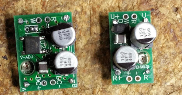
Here's the "finished" boards, I built one of each form factor. The half-wave/full-wave feature was a good idea, and it helps the larger one do better at higher currents. The little one is good for 200-250ma where it's running around 70C, the larger one can do around 500ma for the same temperature. The circuit on the two, other than the lower input voltage rating of the small board's chip, is basically the same design. The difference in the current output is significantly affected by the input capacitance value. Making those bigger would have made the whole module bigger, which went against what I was trying to accomplish. The full-wave option of the larger board gives me more headroom for the input voltage as we have a higher average voltage charging the caps. You'll notice the larger one is slightly lopsided, I actually used thermal adhesive on top of the inductor and the chip to transfer heat to my copper pour on the upper board. For the lower profile chip, I put a small chunk of aluminum on top and used the thermal adhesive on both sides. It just happened that the heights weren't exactly the same. After it was together, I decided that was close enough for a prototype. ![]()
Add Reply
Sign In To Reply


