I am constructing a permanent layout that will includes several vintage Lionel trackside accessories, including the 145 Automatic Gateman, 152 Crossing Gate, and 153 Block Signal.  I intend to ballast and screw down the track, which is O gauge Lionel tubular track. In the past, I used under the track contactors, such as the 153C to operate these accessories, but I'm not sure this is the best option for ballasted and screwed track. I know there are other options to activate these accessories, including insulated track sections, electronic relays, and infrared detectors.

Any suggestions on a preferred method of activation would be appreciated.

Thanks,

Michael

Original Post

Replies sorted oldest to newest

Thanks to all who have replied to this point.  Joe, I gave a quick look at the Circuitron website and it looks like a fine company with user friendly advice. I think I'll be spending some time reading about their products.

As to the insulated track sections, I might go with this route depending upon the cost of the more advanced electronic options. 

Always appreciate the advice on the ORG forums.  Thanks again,

Michael

The Lionel 153IR send an infrared signal across the track which is reflected back by a passing train. It comes with a connection to clip directly onto Lionel tubular track. Looks good too. I've just bought a 153 Block Signal and a 151 Semaphore and I'm planning on experimenting with using the 153IR instead of the supplied 153C contactor.

http://www.lionel.com/products...-controller-6-14111/

And here's a video:

https://www.youtube.com/watch?v=t0mXmPWTLIs

I use the insulated rail method exclusively, just because (1) I'm an old relay type of guy, and (2) that method is the most reliable and flexible in terms of being able to activate and hold a condition, ability to create slow-activate - slow/release situations and the ability to eliminate chattering/flickering of accessories by using D-C relays with filter capacitors.

Thanks for the additional suggestions.  Helpful to see the Lionel video on use of the 153IR unit.  Actually, I like the look of the electrical cabinetry...it's the price for multiple units that does not impress me.  I may go with one or more of these depending upon the accessory and scene, but I think I may use the insulated rail for most of the accessories. 

I am also interested in use of other electronic items with the insulated rail to minimize the chatter of many of the vintage Lionel accessories.  Arthur, can you provide more details on these items (relays/capacitors)?

Thanks,

Michael

Michael Pags posted:

I am also interested in use of other electronic items with the insulated rail to minimize the chatter of many of the vintage Lionel accessories.  Arthur, can you provide more details on these items (relays/capacitors)?

Funny you should mention insulated rail actuators.

Insulated Track Signal Driver

I also sell a kit eight of these you assemble, they're only $8/ea in kit form.

Last edited by gunrunnerjohn

John, this device looks promising and very reasonably priced.  I have some further info and thoughts. 

After considering my layout, vintage accessories, and interests, most probably I will link the 153 block signals to my switches for sidings to highlight the position of the switch.  I am fairly certain this is possible, and it eliminates the need for trackside activation.  I have several units of the 145 gateman and 152 crossing gate, but will probably use only 2 of each due to space limitations (even though these are noisy and not to scale, gotta have them - grandkids love em).  In each location, I will link the gateman and crossing gate to work concurrently.  So in the end, I will probably need only two activation mechanisms for the gateman and crossing gates. I also like to have these activated before the train reaches the units so that they are in operation by the time the train is there.  It appears that the 30100 Insulated Track Signal Device will do the trick.

Question: I think I read someplace that it is possible to eliminate the chatter of the solenoids in these units.  True?  Does the 30100 accomplish this? 

Thanks,

Michael

Yep, one significant benefit of the track sensor was specifically to eliminate contact bounce chatter issues.  You can use a plain AC relay if you don't worry about contact bounce.  However, my goal with this design was to use very low current to activate the relay to minimize the power consumption as well as any arcing as the insulated rail section is entered.

You can read the genesis of the 30100 in this albeit long but recent thread. 

https://ogrforum.ogaugerr.com/...-based-sensor?page=1

As you can see, the 30100 (aka ITSD) was developed with a lot of input from the OGR community.  In addition you can see exactly what you're getting with component-level drawings/schematics.  The sometimes overlooked benefit is if you have a question about how to apply it, there are a lot of guys here on OGR - including GRJ of course - that can help.  

Stan and GRJ,

Thanks for the link to the thread on this issue. Yes, quite long, but interesting. I seem to recall seeing it, but not going very far as this was not on my radar at the time. Well now it is, and I am certainly going to purchase these units.  Just might be back with questions when I get to install them.

Thanks again,

Michael


Sorry for this very delayed post on this thread, but I have been out of the country for several months and only now returning to the layout and this issue.  Having fun again!  I purchased 4 of the 30100 units and just test-wired one on a work bench area to see how it operates.  I can see the benefit of the relay function for trackside accessories with multiple lights like the 153 block signal, but how does this relay differ in function from using just an insulated rail to activate a simple trackside accessory like a 252 crossing gate or 145 gateman?  Does the contact bounce refer to the intermittent conductivity of rolling stock across the insulated section of track or the solenoid noise from these moving accessories?  If the former (and now that's what I think), is there any way to eliminate the latter?  Not a big deal, but just wondering.

Thanks,

Michael


Using the relay method, like the 30100, means less current flows through the wheel axles; that is, the relay contacts do the heavy-lifting in terms of carrying the current.  Consequently you should see less sparking and fewer accumulated "pits" or spots on the rails where the arcing occurs from wheel to track.

As you say, the "chatter" reduction/elimination in the 30100 refers to the contact bounce of the wheels making intermittent contact with the rail.  This typically occurs as the consist enters or exits the insulated-rail section because that's when you may only have one or just a few axles bridging the outer rails and hence more chances to lose contact.

I believe what you mean by the latter "chatter" is the iconic buzzing sound from AC-operated solenoid mechanisms.  In this case the solenoid is typically spring-loaded and as the AC voltage cycles 60 times/sec, the solenoid voltage collapses to zero at that rate (well, twice that rate) at which time the spring pulls back the solenoid pin until the voltage builds up again.  So the chatter is the sound of the solenoid pin/rod vibrating in and out.  As suggested in earlier posts, you might consider using a DC power source to eliminate this type of "chatter".  There are some accessories that depend on this type of AC voltage chatter - such as vibrating platforms (horse corral) or some rotating searchlights.  But if your accessories are DC-compatible, you can pick up a suitable DC-output adapter (a.k.a. wall-wart) for maybe $5 or so.

Stan

Thanks for very helpful reply. Decades ago I triggered these vintage trackside accessories with the classical 153C contact switch so I never experienced the issues using the insulated rail method. I now understand the issue of the contact bounce using that method and that the 30100 will avoid it. And yes, I may look into a dc power source for these accessories. Will not use on cattle car (which I have) as you note. It's a funky and temperamental unit but grandkids love it. 

Thanks again

Michael

OK, I am able to get the 145 gateman to work with the 30100 relay unit.  But now here's a related question: is it possible to have the light in that unit on a separate circuit so that it stays on, not just when triggered with the gateman?  I know it is possible to do this without the relay, but I can't seem to figure that out the wiring for this arrangement using the relay. 

Thanks for any help here,

Michael

PS: I have purchased a DC volt power supply and tried that in this arrangement: no solenoid sound.  Wow, what a difference from decades of the buzzing sound.  So I asked my grandkids which one they prefer: solenoid sound (AC) or quiet (DC), and they said with the sound!  When asked why, one of them said b/c is sounds like the guy is talking.  Although it's good to know I can eliminate this sound on similar units (crossing gate, switch tower, etc), I just might run the gateman units on AC. 

Leo,

Thanks for this incredible resource.  I am a subscriber to OGR magazine, but can not seem to find this resource. Any hints?  BTW, I have some of the original service manuals on these accessories, including the diagram for the 145 gateman using the 145C track contactor.  Great to have this consolidated version.

Will keep trying until I get it right. I know it's possible to wire the gateman and crossing gate (as well as an American Flyer crossing lights), b/c I have done this in the past with the contactor. Just need to figure out how to do this with the insulated track and keep the light in the gateman unit on a separate circuit.

Thanks,

Michael 

In the electrical forum, before the topics of the regular members starts, there are a group of posts from the web administrators and such. The last of these is the Electrical Reference Manuals thread. I found the 1954 Lionel Manual link in a post from Susan Deats. Click on the link in the attachments at the end of her post.

From what I saw in that old booklet, it looks like the gateman light is connected to the two contacts toward the front of the unit. The one in the back looks like the trigger. Accessory AC voltage to those front two contacts should keep the lights on. But I don't know how you have your relay rigged so I'm just guessing.

Yep, one significant benefit of the track sensor was specifically to eliminate contact bounce chatter issues.  You can use a plain AC relay if you don't worry about contact bounce.  However, my goal with this design was to use very low current to activate the relay to minimize the power consumption as well as any arcing as the insulated rail section is entered.


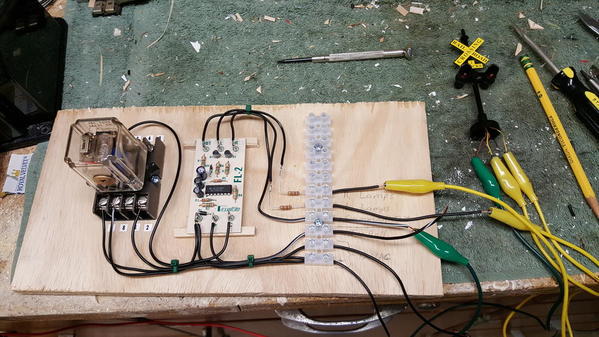
I have a AC relay activating a set of grade crossing signals via an insulated block on tubular track. It that chatters away just as GRJ describes. Gonna pick up a couple of your relays John.

2017-04-09 11.16.06

Attachments

Images (1)
  • 2017-04-09 11.16.06

UPDATE:  Ok, I have had partial success.  This is after countless hours of reviewing the Lionel video on wiring the gateman, downloaded wiring diagrams, and numerous threads on this forum and others.  Thanks for all the suggestions and help.  Here's what I have been able to complete with two separate gatemen linked with adjacent accessories (crossing gate and RR crossing lights):

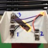
Gateman 1:  Gateman light stays on all the time, even when gateman triggered. Gateman and adjacent accessories triggered by insulated rail.  All on same circuit.  Here's a photo of this set up (FYI, black is ground, violet is power, and orange goes to insulated rail; accessories get violet and orange wires):

Gateman wiring

Gateman 2: Gateman light on, but goes off when gateman and accessories activated. Triggered by insulated rail, but also includes the 30100 unit to prevent contact bounce.  Gateman and accessories on circuit different from 30100 (separate transformers and they are in phase).

I can accept the above operations, but here is my ideal goal:

Gateman light stays on all the time, even when gateman activated.  Accessories activated with gateman.  Accessories and gateman on same circuit, but light on separate circuit.  This permits me to link gateman light with all other lights on layout, and adjust voltage separately as needed for lights and gateman. 

I was able to figure out the wiring and achieve the functions in my ideal goal, but the triggering mechanism was the 153C contactor. Can't figure out how to do this with the insulated rail, and particularly with the 30100 unit.  What frustrates me the most, is that this is not rocket science and I should be able to figure this out!  Sorry if this is a dumb request, but any help here is appreciated.

Thanks,

Michael


Attachments

Images (1)
  • Gateman wiring

The key is common ground wiring where ALL circuits (track, lighting, activation etc) share a common ground and are all connected (either directly or indirectly) to the non-insulated outside rail of your track.

The common ground of the 145 goes to the terminal you marked 1.

Terminal marked 3 is your accessory hot (used for lighting and activation). This should always be "on". Adjusting this voltage changes BOTH the intensity of the light and action of the man. (If you wish to have separate voltages for the light and man, you will need to cut the coil wire from the rod descending from terminal 3. This severed wire can then be connected to a separate voltage for activation.)

Terminal marked 2 goes to the insulated rail (switched common ground) to trigger activation.

This will allow the light to remain on constantly, and activate the man in conjunction with train presence.

Activating other accessories at the same time as the gateman is possible. Take the common ground terminal of that accessory, and connect it (directly or indirectly) to the gateman's terminal 2/insulated rail (switched common ground). Take the accessories "hot" terminal and connect it to the "hot" voltage circuit of choice.


Last edited by bmoran4

I believe I addressed your ideal goal by mentioning you would need to cut the coil wire to separate it out, or I don't quite understand your ideal goal.

bmoran4 posted:


...

Terminal marked 3 is your accessory hot (used for lighting and activation). This should always be "on". Adjusting this voltage changes BOTH the intensity of the light and action of the man. (If you wish to have separate voltages for the light and man, you will need to cut the coil wire from the rod descending from terminal 3. This severed wire can then be connected to a separate voltage for activation.)


...


Last edited by bmoran4

ITSD to gateman

If the ITSD 30100 came with a so-called push-on programming-jumper (which straddles 2 of the 3 pins of J3), you can eliminate the * vertical connection.

I suggest you hook the 30100 and get it running such that the light is always ON, and the gateman is properly triggered by the insulated rail.  THEN worry about issues with adjusting the gateman voltage separately from the light voltage or whatever.

Attachments

Images (1)
  • ITSD to gateman

You absolutely did!  I only read the post as it came directly to my email, which ended with the sentence "Terminal marked 3.."  and posted the reply based upon that limited info.  I did not read your entire post on the forum before I replied.  Sorry.  I'll be sure to access the forum before replying in the future. 

I have seen this approach and thought I tried it without success. Will try again following your details.

Thanks again,

Michael

Stan,

Extremely helpful.  The 30100 did not come with the jumper, but this was described in the literature that came with it.  I did not completely understand it then, but now this makes sense. I actually have a jumper wire in the screw in terminals in the 30100 in Gateman 2.   I'll give this a try, b/c I would prefer to include this unit in the operation of both gateman units. 

Also, just as an FYI, I had considered changing over to an IR triggering mechanism, but decided against that, b/c the mainline has 2 reversing loops and I want to trigger the accessories from a distance when trains run in each direction. The insulated rain mechanism seems to achieve this better.

Thanks,

Michael

Michael Pags posted:
...

Also, just as an FYI, I had considered changing over to an IR triggering mechanism, but decided against that, b/c the mainline has 2 reversing loops and I want to trigger the accessories from a distance when trains run in each direction. The insulated rain mechanism seems to achieve this better....

Right.  You would generally need two IR triggering devices to sense entry from both directions so reach deep into your wallet unless you roll-your-own.  

To your point, some accessories can indeed be tricky to wire-up to two IR devices because they can "conflict" - that is, one trigger saying "occupied" and the other trigger saying "unoccupied".   

Latest and greatest: Success for Gateman 1!  I followed suggestion from BMORAN4: cut wire descending from terminal 3 in my photo and connected to power supply separate from light.  All works great: can separately adjust power to light (which is linked to bus for lights on layout) from the power supply to gateman (linked to power supply to other gateman).  Adjacent accessories also linked to gateman power and action. 

Now on to Gateman 2 to see how I can incorporate the relay unit. If I can figure that out following Stan's great diagram, will use that arrangement for Gateman 1. 

Will post after I get some sleep...

Michael

Add Reply

Post

OGR Publishing, Inc., 1310 Eastside Centre Ct, Suite 6, Mountain Home, AR 72653
800-980-OGRR (6477)
www.ogaugerr.com

×
×
×
×
Link copied to your clipboard.
×
×