
Airpax Large

DISCLAIMER: This topic is for discussing these types of breakers.  The 10A "Instant trip" example pictured above might not be right for your application.  Choosing the right Amperage rating and Time delay should be based on several factors and less than or equal to the nominal output rating of the transformer to which they are connected.  If you think you may want to use a breaker of this style and you are unsure of the correct model, please ask for help here in the Electrical Forum  in choosing the right one for your application.


Airpax Snapac Hydraulic-Magnetic Circuit Breaker Internal Mechanisms - Updated 12/4/2021

Introduction:  These very fast acting circuit breakers are ideally suited for use in helping protect the sensitive electronics within modern Locomotives (TMCC/Legacy, Lion Chief (all versions), DCS, ERR and others especially when power is supplied from postwar transformers. These Airpax breakers are ideally suited to use on a layout when a mix of Command and Conventional Locomotives are run.

The Airpax "Instant" models presented here will trip in 1/10th of a second when their rated current (in Amps) is exceeded.  They are faster than fast blow fuses and much faster than the original internal Thermal breakers that came stock inside postwar transformers.

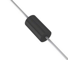
The other part of helping protect locomotives' electronics is combining fast acting breakers with TVS (Transient Voltage Suppression) diodes located strategically around the layout.  Since there are numerous other references on this Forum, I will not go into detail about those here.

When I first read about these products here on OGR in early 2021, I decided to learn more about them. This series of hydraulic-magnetic breakers is called AirPax Snapac and is made by Sensata/Airpax.

Their data sheet is attached below.

There is more information on the web about their larger cousins (for example https://www.youtube.com/watch?v=sJU2pTdUyY0 ) used for higher voltage and amperage circuits, how they work and cut-away animations, but I was unable to find details on the inner workings of these smaller Airpax Snapac hydraulic-magnetic versions.

I decided to cut open one of the Airpax Snapac 10A “Instant” trip breakers. They are very similar, in that they have an Arc Chute (for dissipating the arc created by the opening contacts when they trip). They also have what appears to be a gas filled piston inside a coil, but there is one subtle difference in the way it activates the trip linkage. As the current in its stationary coil rises towards a set value, the resulting increase in the magnetic field overcomes the spring tension on the disconnect mechanism and pulls on a lever and disengages the contacts.

AirPax Cutaway3AirPax1

Airpax Snapac hydraulic-magnetic breakers are available with different time delays before tripping at the rated current (Amps). They come in Instant                       ( 100 millisecond delay), Fast (slower than the Instant and the delay time varies by how much above the rated current the actual current flow through them is for a variable period of time), and Slow (which has delay characteristics similar to a Slow Blow fuse).

Choosing the right type of breaker is dependent upon many factors and choosing correctly can mean the difference between experiencing nuisance tripping before the the optimal current flow is reached in the protected circuits, to just right protection, to being either to slow or overrated and not providing adequate protection to prevent damage to the transformer and what's connected to it.


Here are links to the Airpax Snapac "Instant" trip Series Breakers


5 Amp   PP11-0-5.00A-OB-V   https://www.onlinecomponents.c...00aobv-10090638.html or https://octopart.com/search?q=...ency=USD&specs=0


7.5 Amp   PP11-0-7.50A-OC-V   https://www.onlinecomponents.c...50aocv-10090644.html or  Link to Alternative overseas Distributor or https://octopart.com/search?q=...ency=USD&specs=0


10 Amp   PP11-0-10.0A-OB-V   https://www.onlinecomponents.c...00aobv-10090622.html or https://octopart.com/search?q=...ency=USD&specs=0


12.5 Amp (no button markings)   PR11-0-12.5A-XX   https://www.onlinecomponents.c...125axx-43802931.html or https://octopart.com/search?q=...ency=USD&specs=0


Links to the Fast and Slow varieties are not included here, but can be found on the same website. Their part numbers differ by having a PP11 -1 - xxxx(Current rating) for Fast, and PP11 -2 - xxxxx(Current rating) for Slow.


Here is some basic information on choosing the correct Amperage rating for a breaker:

There are a few electrical fundamentals in addition to the trip delay time one should understand when choosing a breaker. The transformer Output ratings are a good place to start.  Here's what they mean:

Volts - (electrical energy potential) in Conventional operation this sets the train speed.
Amps (current flow) - More Locos, cars and such (and shorts) pull more current through the circuit from the transformer.  The transformer only delivers as much current as required by the load, up to a point.  This point is it's Output rating.

AC Transformer Output ratings are usually given in either Watts or VoltAmps, both of which have essentially the same meaning when choosing breaker size.

Watts = Volts x Amps = VA
or

Watts/Volts = Amps


An often asked question is how to connect a Circuit Breaker and TVS Diodes.  Here is a very basic example of a simple loop connected to one transformer:

Track Connections2a

If you're looking for the ultimate in protection for your Legacy locomotive's electronics, installing TVS diodes inside the locomotives, on the PCB track power inputs is the best way to protect their sensitive electronics.  TVS installed on the transformer outputs is a good step, but high frequency voltage spikes will travel past these.

Here's a link to the Topic started by Adrian! and his explanation of how this happens:

Words about TVS Placement

from that topic:

TVS

I hope this helps.

Attachments

Images (5)
  • Airpax Large
  • AirPax Cutaway3
  • AirPax1
  • Track Connections2a
  • TVS
Files (1)
Last edited by SteveH
Original Post

Replies sorted oldest to newest

I can’t answer your questions, but I will say that those 10A breakers might be too slow.  I got some Airpax Snapak breakers a few years ago.  They were too slow.  Mine are PP11-2, so your PP11-0 breakers may be faster.  I ended up replacing them with Eaton-FAZ-B breakers (3, 4 and 5 amp) and I’m happy with them.

@Lehigh74 posted:

I can’t answer your questions, but I will say that those 10A breakers might be too slow.  I got some Airpax Snapak breakers a few years ago.  They were too slow.  Mine are PP11-2, so your PP11-0 breakers may be faster.  I ended up replacing them with Eaton-FAZ-B breakers (3, 4 and 5 amp) and I’m happy with them.

Thanks for that insight and a good point. The second part of the model number indicates the trip delay.  The -0 is supposed to be "instant".

airpax delay

The time delay plots are on page 65 of the data sheet.

Attachments

Images (1)
  • airpax delay
Last edited by SteveH

It was offered as a rebuttal to the notion that we need to immerse ourselves in never-ending hand-wringing over trying to make the electric toy train hobby resemble NASA projects.  If electronic components of toy trains are not robust enough in their design or applications, then we need to rethink the design and applications, not fret over multi-dollar protection devices that the manufacturers apparently didn't seem to feel necessary.

As has been explained many times by the electronic experts here, there are only a few things we can do to protect the fragile electronics inside a locomotive, should a fault occur outside the locomotive. The cure to the perceived or real volatility in the electronic components is to source them and design their circuitry so as not to be susceptible to external faults.

My remarks were offered, as are most here, in the spirit of getting a conversation going. They were not made to deride "modern electronics" whatever that means. They were, however, made to try to poke the manufacturers into getting their act together.  My favorite "fix" has been the "add a light bulb and see if that helps" mentality.

Last edited by Arthur P. Bloom

@Arthur P. Bloom I want to thank you for your opinion.  You are certainly welcome to manage your model train layout in the way that you'd prefer.  There is no intent on my part here to tell you or anyone else otherwise, and I respect everyone's decisions even if I may not agree.  I'm not trying to tell anyone to over-complicate the way they might desire to wire their layout.  I'm also not trying to convince you or anyone to change their way of thinking about this.  I am trying to learn specifically about how these breakers function.

Rather than continue debating your points of view on this thread, would you please consider starting your own topic to discuss your grievances about your opinions on complexity?

For the sake of any newbies who may be following this thread:

(1) Fuses and circuit breakers are neither new nor novel.  In particular they have not been introduced in recent years as "band aids", and have never been considered such at any time.  They are a fundamental part of electrical safety and have been so since electricity was first harnessed in the 1800's.  This is very, very mature technology and is depended upon every day in thousands of applications, in industry, transportation, offices, homes, and yes even toys. 

(2) Safety does not concern only whether your locomotive or accessory quits.  Your electric train has the capacity to, and very likely has in at least one case in the past, burn(ed) down a house, or at least started a significant fire.  (If it hasn't, or couldn't, why would a safety organization like Underwriter's Laboratories (UL) be so involved with toy train transformers for all of these years?)

My apologies for elevating the discussion.  This is not a political rant.  These are hard-and-fast technical facts.  (This forum has proven to be very helpful in disseminating the important technical facts if you just let it.)

M.H.M.

This is an important discussion as I am always looking for better ways to protect the very  expensive electronics in my trains.   An ounce of prevention versus the pound of cure.  Anytime I see a post on this topic I read and reread making notes that could possibly protect my trains and my layout.

Thanks for bringing this up.

Last edited by Keith k

As has been explained many times by the electronic experts here, there are only a few things we can do to protect the fragile electronics inside a locomotive, should a fault occur outside the locomotive. The cure to the perceived or real volatility in the electronic components is to source them and design their circuitry so as not to be susceptible to external faults.

The Lionel PowerHouse 180 has a fast acting (maybe instantaneous?) breaker.  However, none of the postwar transformers have these, nor do many other modern transformers. There have been multiple discussions about this these Sensata/Airpax magnetic and magnetic-hydraulic breakers, as well as similar ones from Carling Technology.  The goal, as I see it, is to add a comparable level of protection to these older transformers. 

While TVS diodes are a good idea, and highly recommended, in the case of a short circuit, the safest and surest way to avoid damage is to remove the electrical current as quickly as possible.  That is the purpose of these circuit breakers.

Why toss/junk a perfectly good transformer, and spend $100+ when a $20 breaker can remedy this?

Steve, I had a link for octaport.com but I’ve lost it, ....lots of data on that page........I too found them too slow, but have not tried the -0 TBT,....I’ve tried these in the automotive world for different applications and found the release too slow holding voltage on the consumer as it tripped,....didn’t like that, especially with sensitive components that don’t react well to voltage drops,....hope that helps,..

Pat

@SteveH posted:

@harmonyards Pat, thanks for the tip about Octopart.com.  It looks like a good resource for finding who has what parts.  I'll look at it some more to see if I might be able to find a link to a cut-away for the Airpax.

For your notes, on the flip side, we found the reset to be very clean, zero lag, leap years ahead of any thermal breaker,...( normally used in our world) it’s the release we had issues with.....holding voltage on sensitive, and expensive fuel pumps in the performance world.......we were looking for alternatives to ATO’s and fast blows that don’t always react at their “advertised load rating” ........we’ve settled on Eaton breakers and found them a lot faster on the release side, .......I believe another fella mentioned them above as well,....

Pat

Arthur... I'm not speaking for you OR your wise observations.  However, electronics has grown since the early days of RADIOSHACK. So have the complexity of our trains.

I know there are many, a lot of my friends, that wish to go back to those early days where the most advanced electronic gadget was a door-bell circuit. Once again, those days are over and done.

To advance the hobby, a few of us not all, need to get our heads out of the sand.

@harmonyards posted:

For your notes, on the flip side, we found the reset to be very clean, zero lag, leap years ahead of any thermal breaker,...( normally used in our world) it’s the release we had issues with.....holding voltage on sensitive, and expensive fuel pumps in the performance world.......we were looking for alternatives to ATO’s and fast blows that don’t always react at their “advertised load rating” ........we’ve settled on Eaton breakers and found them a lot faster on the release side, .......I believe another fella mentioned them above as well,....

Pat

Pat, unless I'm misunderstanding your meaning, I think we might be talking apples, oranges, and bananas here on the time delay.  The other mention above was for a slow trip time Airpax with the number 2 in the second part of the model number ( PP11 - 2 - **** ).

There's also the "fast" delay option ( PP11 - 1 - **** ) with a trip curve that sounds like what you could be describing.

If you look closely at the picture in the original post, its a PP11 - 0 - 10.0 - OB -  V which is the instant fruit (I mean delay) . The  - 0 = "instant" PN designation Airpax breaker is supposed to disconnect the load in less than 0.001 second ( 1 millisecond ) if current flow to the load rises above its rating.

Instant Delay Air Pax

Do you think the ones you were using might have been the ( PP11 - 1 - **** ) "fast" that has a curve like this?

Fast Delay Air Pax

Attachments

Images (2)
  • Fast Delay Air Pax
  • Instant Delay Air Pax
Last edited by SteveH
@SteveH posted:

Pat, unless I'm misunderstanding your meaning, I think we might be talking apples, oranges, and bananas here on the time delay.  The other mention above was for a slow trip time Airpax with the number 2 in the second part of the model number ( PP11 - 2 - **** ).

There's also the "fast" delay option ( PP11 - 1 - **** ) with a trip curve that sounds like what you could be describing.

If you look closely at the picture in the original post, its a PP11 - 0 - 10.0 - OB -  V which is the instant fruit (I mean delay) . The  - 1 = "instant" PN designation Airpax breaker is supposed to disconnect the load in less than 0.1 second if current flow to the load rises to above about 135% of its rating.

Do you think the ones you were using might have been the "fast" that has a curve like this?

Fast Delay Air Pax

The -1 is the one we tried on a 12-14V circuit, ( 13.90 running ) on a 20 amp service,.... ....I believe you’re correct, we’re probably comparing apples to oranges,....when we forced a trip, and observed the drop out, it was not instant, almost as if the arc was holding load as it moved away from the contacts,.....we bought them since they were cheap, and  I could certainly cut one open if that’s the exercise of the thread,......  

Pat

@harmonyards posted:

The -1 is the one we tried on a 12-14V circuit, ( 13.90 running ) on a 20 amp service,.... ....I believe you’re correct, we’re probably comparing apples to oranges,....when we forced a trip, and observed the drop out, it was not instant, almost as if the arc was holding load as it moved away from the contacts,.....we bought them since they were cheap, and  I could certainly cut one open if that’s the exercise of the thread,......  

Pat

Pat that would be Great!

Having a look inside would certainly answer the main 2 of the 4 questions.

@SteveH posted:

Pat that would be Great!

Having a look inside would certainly answer the main 2 of the 4 questions.

When I go back to work on Monday I’ll grab the one that looks very similar to the one pictured at the top of this thread,...when my customers spend 900-1100 bucks on fuel pumps, they’re very interested in circuit protection ( obviously why) ......we designed an overkill circuit that consists of ATO fuse ( which most of us know can be pathological liars ) , breaker, and inertia breaker ( another Eaton product) for case of collision.....FoMoCo already uses the inertia breaker in circuit so we cheat like heck and borrow their plans,....😉

Pat

Steve I have enough knowledge about electrical to be dangerous and I have not heard arc shoots in twenty years.  I will try to answer your questions about that since you have waded into the area of serious circuit breakers.

A couple of simple observations. No such thing as an instantaneous breaker. The breaker has two pieces of metal and when bad things happen they open.  There is always an arc between the contacts until they are far enough apart. In large heavy duty breakers it takes a serious gap for the arc to stop. Hence the need for shoots. I would guess a minor factor in train applications.

Back  to your original questions go back to Pat and John, speed and the curves on time.

Back feed well we have had cases when motors turned into generators and that wreaked havoc but not a concern with train motors.


@rplst8 posted:

I couldn’t find anything in stock at Digikey or Mouser that was instantaneous from Eaton when I looked a few days ago, but this doc below has a cut away of their AR series breakers and they specifically talk about extinguishing grids to control arcing. Is that sort of the feature you were looking for @SteveH?

https://www.eaton.com/content/...eries-ca130003en.pdf

Ryan, than you for looking for a solution and the link.  Eaton's extinguishing grids do appear to perform the same or similar function as an Arc Chute and Arc Dissipation Plates.  I'm hoping we'll also get to see and understand what's inside the Airpax Snapac specifically and if it's any different from others.


@harmonyards Pat, thank you for offering to cut open one of your older Airpax breakers.  I look forward to seeing your pictures of it.


Cal, thank you for your insights and reply.  Please see my comments and questions below within your quote box.

@Caldwell posted:

Steve I have enough knowledge about electrical to be dangerous and I have not heard arc shoots in twenty years.  I will try to answer your questions about that since you have waded into the area of serious circuit breakers.

A couple of simple observations. No such thing as an instantaneous breaker. Yes that's absolutely true, these claim a trip time of 0.1 seconds = "Instant". That's why every time I have used that word I put it in quotes. The breaker has two pieces of metal and when bad things happen they open.  There is always an arc between the contacts until they are far enough apart. In large heavy duty breakers it takes a serious gap for the arc to stop. Hence the need for shoots. Understood  I would guess a minor factor in train applications. Probably so, but there is still an arc that would cause pitting on the contacts if not dealt with in some way.  These Airpax breakers have an endurance rating of "in excess of 50,000 cycles..." (which is reduced by higher voltages and current loads).  So, until Pat looks inside, we may not know exactly how these breakers absorb the arc energy.

Back  to your original questions go back to Pat and John  (John?), speed and the curves on time.  Not sure what you mean here, but I do understand the trip curves for the 3 delay types and my original questions are unrelated to time delays.  Would you please clarify what you're saying if unrelated to trip delay curve?

Back feed well we have had cases when motors turned into generators and that wreaked havoc but not a concern with train motors.  My understanding is that back feed can and does occur in both cases (just many orders of magnitude less in model trains).  In the case of a derailment, the generated voltage spikes can be much higher than normal operating voltage due to two or more motors' rapid field coil discharge currents.  Of course, this can be diminished when TVS diodes are strategically placed within the circuit (but TVS has been well covered elsewhere).

The back feed conditions I was trying to ask about were unclear.  What I'm wondering is:

Even though there are other very good reasons not to do so (and not the question being asked), are there any reasons why permanently connecting a 120 - 240V AC Hydraulic-Magnetic circuit breaker backwards (ie. line terminal connected to the load and vice versa) might diminish is rated service life (endurance = number of cycles before failure)?

and

Does a 120 - 240V AC Hydraulic-Magnetic breaker containing an Arc Chute dissipate a breaking arc current which might flow into the breaker from either Terminal (Load and/or Line sides) by routing the arc thorough the chute, regardless of which pole the current enters?

Thank you again to all who've contributed to this topic so far.

OK... a stupid question from an electronic idiot.

I have used the digi-key breakers for quite some time on my pre & post war transformers... and, apparently I am incredibly lucky as I have to date, never blown a board or compromised the functionalities therein.  I certainly must have crossed the derailment threshold to provide ample opportunities to attain a blown board.

Which breaker will trip first... the 7amp digi-key or the 10amp breaker discussed herein?

Excellent Thread BTW... THANK YOU!

Dennis, the 7A breaker you're talking about is a Potter & Brumfield W28-XQ1A-7 for use in slow-blow applications.  It uses a different Thermal Magnetic internal mechanism to operate than the Airpax.  The P&B is also heat dependent, where the Airpax isn't.

Potter and Brumfield Breaker Features

In the P&B, as the current flow through it rises above the rated trip value, it would be much slower to open the circuit than an Airpax so-called "instant" breaker with a comparable current rating.  Here is the Trip delay curve from the Potter & Brumfield W28 series datasheet:

Potter and Brumfield Trip curvejpg


I've not seen a trip delay curve for the breakers built into the PW ZWs (when they were new) but I'm guessing it's close to the same as the external circuit breakers you have.  If you're running TMCC, DCS or Lion chief equipment around the Christmas tree, some faster breakers, might be worth considering, (as well as an Adult proof railing ).  Postwar type Locos, might be fine as is.

Attachments

Images (2)
  • Potter and Brumfield Breaker Features
  • Potter and Brumfield Trip curvejpg
Last edited by SteveH

@SteveH ....I've not seen a trip delay curve for the breakers built into the PW ZWs (when they were new) but I'm guessing it's close to the same as the external circuit breakers you have.  If you're running TMCC or Lion chief equipment around the Christmas tree, some faster breakers, might be worth considering, (as well as an Adult proof railing ).  Postwar type Locos, might be fine as is.

no need to worry about trip curves on PW ZW’s....when my stick welder fails out in the garage, I use my trusty ZW to weld things back together!..🤣🤣🤣🤣🤣🤣

even with the fastest breaker on earth, diode suppression still might be a good idea as a back up plan, to keep the harmful shot from heading in the wrong direction.....

Pat

Unfortunately I don’t have the knowledge to add to this very informative discussion, however when all is said and done it would be great to have a list of components and a diagram on how to incorporate these items.  That would include breakers, diodes and tvs’s.         Thanks to all the knowledgeable people for making this post possible.

@Keith k posted:

Unfortunately I don’t have the knowledge to add to this very informative discussion, however when all is said and done it would be great to have a list of components and a diagram on how to incorporate these items.  That would include breakers, diodes and tvs’s.         Thanks to all the knowledgeable people for making this post possible.

Keith, that's a good suggestion. However, it might be difficult to come up with a one size fits all diagram, for all the possible breaker applications encountered in a model railroad layout.  But there are some general points that could be addressed in your suggestion.  Also, FWIW the diodes Pat mentioned are the TVS (Transient Voltage Suppression diode).

Last edited by SteveH

Thank you much guys!

I run some Conventional.  My Legacy & TMCC Locos run via Legacy (no tiu/aiu/dcc/dcs etc).  I guess I've just been really, really lucky through all the derails with the TMCC & Legacy Locos.  I did grab a ZW-L that provides track power to the new permanent layout.  I'll keep an eye on this thread and upgrade the protection on the pre/post transformers once you guys nail this down.  Thanks again for your great work and service to the community.

As an experiment, I set up my layout about 10 years ago with a "textbook" TMCC/Legacy arrangement, each 180 watt brick is connected to a Legacy Powermaster, using the recommended Lionel cables and fuses, with absolutely no other breakers, fuses, TVSS diodes or anything. No electronic failures so far despite the typical share of derailments and tools on the track. I run Legacy, TMCC, Lionchief Plus and a tiny bit of conventional.

The protection in the 180 watt bricks is fast, but the Legacy Powermaster is even faster, it is almost impossible to trip the breaker in the brick; the Powermaster almost always trips first.

No pre-war/post-war transformers involved. Personally, I think pre-war/post-war transformers are the root of a lot more electronic evil than is generally appreciated.

YMMV.

You're probably right, I run with the PH180 bricks through the TIU and on to the tracks.  I get even more protection as each TIU channel has a TVS on the output.

We've also run our modular club that way since it was formed about ten years ago.  We don't have electronics dropping like flies, even though that environment has generous amounts of shorts, bad connections, derailments, etc.  If you think you have track or derailment issues on a fixed layout, try clamping 20+ modular sections together with a couple of C-clamps each and running on that!   Yes, we also have lots of tools and other debris on the tracks from setup and repair before the show, that takes it toll.

After cutting open one of the 10A "Instant" and doing some testing with it, my questions have been answered.  I've updated the first post in this thread with these findings and the internal pics of it, if anyone else might be interested.  There are also links to where the instant series can be purchased, as of now.  The 7.5 and 10A are in short supply.

Link Back To Top

Thanks for that , about what I expected, but now I know for sure what's in them.

About what I expected too, but the tiny U-shaped arc chute is cute.  It's also interesting to me that the coil assembly is stationary.  IMO a good compact design for low current applications.

It's also noteworthy, that when connected directly across the ZW outputs inline with an analog Ammeter,  the 10A instant breakers (tested both with 1 and 2 connected in series) tripped (simultaneously) as soon as I barely opened the ZW throttle.  The needle on the ammeter barely moved, as should be expected.

Also tested with a with a 5A fast blow fuse in one of the test leads, and if the throttle was rapidly opened to about 12V, the breaker would trip leaving the fuse intact.  At 6V ( and ~ 30 ohms in series) the fuse blew first.

Last edited by SteveH
@Windy City posted:

I am just getting back into the hobby and have several Allen Bradley model 1492-GH100 single pole circuit breaker.

I have no idea who recommended them.  Please share any information.  

Unable so far to find much info on these, except that they are thermal magnetic and rather pricey. No data found on their trip characteristics.

Maybe if you were to Post a new topic indicating that you're looking for info on these specific breakers, that might grab more attention.

SteveH ... appreciate the research and insights of your series of posts.  I run Lionel Legacy Command locomotives.  I have been using ATO Smart Glow Blade Fuses for the past couple of years between my Z4000 transformer and Gargraves track ... https://www.mouser.com/datashe...datasheet-461533.pdf   My consists typically draw ~2 amps on the inner loop and ~2 amps on the outer loop.  Two years ago I opted to go with 5 amp ATO Smart Glow Blade Fuses.  The vendor rates them as "Medium/Normal Blow".  At the time I figured going with 5 amps would give me some margin for track short circuits.  I also have TVS's about every 7 feet around my two track ovals on a 15ft x 10ft track layout.  Have had probably 15-20  trips of my 5 amp ATO fuses in the past 2 years ... and ... so far, no known damage to loco electronics.

However, after reading through your post, I became a believer in the Airpax Snapac for a fairly reasonable cost.  I just went online to the site you identified and ordered the 5 amp Airpax Snapac circuit breakers     Having now compared the 5 amp ATO Smart Glow Blade Fuse datasheet time-current characteristics (in above pdf) to the very fast Airpax Snapacs, I expect the 5 amp Airpax Snapac will trip before the 5 amp ATOs for my normal track short circuit snafus.    I also bought a couple of 7.5 amp Airpax Snapac in case I start getting nuisance trips with the speedy-tripping 5 amp Airpax Snapacs. 

I will wire them up in series with my 5 amp ATO Smart Glow Blade Fuses.  I'll post my anecdotal experience with these Airpax Snapacs vs my ATOs upon receiving them and running my layout for a month or so.  We will see.

Thanks again for a well-done analysis.

Regards,

Tom

SteveH:

Thanks so much for all of this information. I am replacing my "fast blow fuses" with the Airpax Snapac instant trip units you identified.

So far I replaced 5 fuses and when testing found them to be very fast! My (brick) transformers are the Lionel 135 Watt units which is why I installed the quick blow fuses.

I considered replacing the 135 Watt bricks with 180 Watt bricks to have the faster breaker as many have attested to here on the Forum. Since I didn't need the extra power it made perfect sense to install the Airpax Snapac instant trip breakers for less hassle and cost.

To say the least, it has been quite annoying to replace a blown fuse after a derailment, particularly when guests were visiting. Now, re-setting a breaker is really a "snap"!

Best regards,

Stan

Last edited by stangtrain

I just finished installing another 4 of these nice very fast breakers. Now all circuits are well protected together with a TVS on each:

356E38A0-3973-45BB-A300-7E38D8861DBA

Here is the power distribution center prior to the upgrade to the circuit breakers. It was a little tricky making the small panel for the breakers fit in the small space above where the fuses were, but wiring was pretty easy:

IMG_4189

Attachments

Images (2)
  • 356E38A0-3973-45BB-A300-7E38D8861DBA
  • IMG_4189
Last edited by stangtrain

Steve, I have a question.  I'm building a small portable conventional layout with one loop of track and one siding.  It is broken into 4 blocks so that you can switch from the running engine to one parked on the siding, so basically I'll only have one train running at a time.  Would one circuit breaker be enough protection for all of the track or should I put one on each block?  Oh, this is being built on a hollow core door, so it's a really small layout.

Thanks!

I agree with John that one breaker for your layout should be sufficient, unless you're providing power with more than one source.  If you're using more than one transformer or multiple outputs (ie. one for trains and another for accessories), then I'd suggest one breaker per output, especially if you're using a post-war transformer.  What transformer(s) are you using?

The whole layout is designed to be powered by one transformer, either a PW KW, ZW, or an MRC Pure Power Dual.  The layout is designed so that they are all interchangeable.

Below are a couple of pictures so you can have a visual.  I hope I'm doing this right, it's my first time posting photos here.  The first one is an earlier picture and the second one is after I finished the frame and control panel.  The transformer just sits on the control panel when in use and is removed before the control panel gets folded up for transport.  I was just starting the wiring when I read about TVS diodes and circuit breaker protection here on the forum.  My last layout was about 25 years ago and all I used then was what ever my transformer came with.  And yes, I do think I have a thing about toggle switches.

Attachments

Images (2)
  • Door Layout 1
  • Door Layout 2
@31charlie posted:

The whole layout is designed to be powered by one transformer, either a PW KW, ZW, or an MRC Pure Power Dual.  The layout is designed so that they are all interchangeable.

Below are a couple of pictures so you can have a visual.  I hope I'm doing this right, it's my first time posting photos here.  The first one is an earlier picture and the second one is after I finished the frame and control panel.  The transformer just sits on the control panel when in use and is removed before the control panel gets folded up for transport.  I was just starting the wiring when I read about TVS diodes and circuit breaker protection here on the forum.  My last layout was about 25 years ago and all I used then was what ever my transformer came with.  And yes, I do think I have a thing about toggle switches.

Charlie,  while not necessary, you could power the uncouplers from another (Aux) source than the one controlling the trains.  That would allow you to supply the optimal 10-12 volts to the uncouplers while providing independent speed control the the train either conventionally or 18v for TMCC/DCS/LionChief.  In any case, a second breaker could optionally be used for the Aux power.

Hi SteveH,  Thanks for the idea.  I've thought about powering some things on the layout from another source but since I want this to be portable I think I'll just use one transformer to power it all.  With my KW I'll have 190watts available, and more with the others if I use one of those, I don't think I'll over tax any of them with what I have.  Everything I'll be running will be in conventional transformer control except for when I use a LionChief engine which I can still power with any of the transformers I'll be using.

Please let me know if you have any more thoughts or ideas for me.  I'm at the point where I'm ready to start wiring things up.

@31charlie, I don't want to belabor the point, just trying to ensure sure you understand your options.  You could use any single one of the 3 transformers you mentioned to provide power separately for the trains and for auxiliary devices.  Each one of those (ZW, KW, and MRC-Dual) transformers has multiple outputs.  Each output could use its own external breaker if you don't want to rely on the breaker built into the transformer.  My thinking was that I'd pay about as much for shipping as one breaker costs, so I bought a few more than I thought I'd need.

But, again the choice is entirely up to your personal preference.

@31charlie posted:

Hi SteveH, So your saying to put a breaker on every feed from source to the load?  Even for accessories?  I must admit that I didn't really think of this before, I was only thing about a train derailing or some thing like that.

I'm not saying you should.  Rather, that I would since there is a chance that a misaligned pick-up shoe or roller could catch the accessory power from one of the auxiliary rails on an operating track.  If that happened, the only thing to cut the power would be the transformer's internal breaker. The PW ZW and KW are slow to trip, and take long enough to melt the insulation on small wires in modern locos and accessories.  I'm not sure about the speed of the MRC's breaker.

In other words, adding additional breakers (one per connected output) is cheap insurance if you're already planning to buy/install one breaker anyway.

Thanks SteveH and GRJ!  I never thought of about the accessories causing a problem.  I'll be adding breakers to all the circuits on the layout.  It looks like the Airpax breakers will perfect for my needs.

I'm really glad I ask about this before I started the wiring, this has the potential to save me a lot of problems in the future.  Thanks again to the OGF, this really is the best resource for information on O gauge trains!

I would just like to add that I use two PC power supplies to power almost all my accessories. I can't attest to the exact type, but they have electronic circuit protection. I can short a 30 awg wire and it trips instantly. I use a 3 amp thermal breaker to protect small wiring, but it has never tripped. I use the 12v and 5v taps for all relays, signals, and lighting (90% led).

For anyone looking for fast circuit protection this time of year, I've added a few updates to the original Topic including the diagram below showing a simple example for how to connect a circuit breaker and TVS diodes.

Track Connections2a

For convenience, here is a link back to the beginning of this thread.  Airpax Snapac "Instant" Hydraulic-Magnetic Circuit Breaker Internal Mechanisms


Attachments

Images (1)
  • Track Connections2a
@SteveH posted:

The P&B is also heat dependent, where the Airpax isn't.

Hum!  A tangential question:  Are automotive self-resetting breakers, such as used to upgrade the internal breakers in ZW transformers, heat dependent as well?  If so, that may explain a problem I've had in the past where a ZW has been running for a few hours and then the upgraded breaker pops with no provocation... 

Mitch

Most of those style breakers are thermal breakers and are just fine for protecting the transformer as originally engineered and intended.

These AirPax breakers are external breakers and strategically sized and placed for sub circuit protection and of course, are very very fast in tripping and can be considered as adding some additional downstream protections.

Last edited by bmoran4

@Carl J I'm using the 10A with my PW ZWs for track power.  Presently Online Components is out of stock on the Airpax Instant 7.5 Amp breakers.  There are other distributors for Sensata/Airpax, but beware similar part numbers that are not of the Instant variety (see earlier replies).  Maybe someone can find the 7.5Amp Instant elsewhere.

For accessories a lower current rating may be better depending on which and how many.  The 5A may work for those, depending on the required power.

Last edited by SteveH

I prefer the 10Amp breakers on the postwar ZW for track power because they allow more operational flexibility, ie. more than one locomotive (conventional, LC, and/or Legacy) on a power district track a time with smoke and incandescent lit passenger cars.

In a more general sense of choosing a breaker's current rating, as long as the transformer's output current rating is not exceeded, any of the Instant breakers will trip immediately in the event of a derailment.

When TVS diodes are installed appropriately, I'm inclined to believe there's little benefit to choosing a smaller breaker for added train protection, if the selected instant breaker is rated approximately 20% less than the Postwar transformer's maximum output current.  Thoughts?

Last edited by SteveH
@SteveH posted:


I'm inclined to believe there's little benefit to choosing a smaller breaker for added train protection, if the selected instant breaker is rated approximately 20% less than the Postwar transformer's maximum output current.  Thoughts?

There can be perfectly acceptable scenarios that lend themself to having a ZW with four 10A breakers hanging off of it and there are others where that would be inappropriate. That is why I always recommend, with the goal of protecting the downstream equipment, one sizes the instant breakers to the downstream load and never let the total load exceed the transformers capabilities (sure a 20% de-rating parameter can be utilized in determining the capabilities).

@Stephen G, you don't provide an exact model number or series of the breaker. The common ones seem to be W28 and W58 (and there are others I am sure) and those are thermal breakers and do not even compare to the instant breakers discussed here. If your goal is protecting downstream equipment with some of the fastest trip times reasonably obtainable, these AirPax are the bees knees and are what I have been using personally for 7 years or so now.

Last edited by bmoran4
@bmoran4 posted:

There can be perfectly acceptable scenarios that lend themself to having a ZW with four 10A breakers hanging off of it and there are others where that would be inappropriate. That is why I always recommend, with the goal of protecting the downstream equipment, one sizes the instant breakers to the downstream load and never let the total load exceed the transformers capabilities (sure a 20% de-rating parameter can be utilized in determining the capabilities).

I understand that with accessory loads the breaker should be sized for the intended load.  I'm wanting to understand your statement about other inappropriate scenarios.  Where it applies to protecting the train's electronics (with judicious use of TVS diodes), can you provide some examples of when using a 10A instant breaker might not be appropriate?

@SteveH posted:

can you provide some examples of when using a 10A instant breaker might not be appropriate?

I realize some of this strays from your exact ask, context, and bounds, but spelling it out for the benefit of the forum at large:

  • Any classic Lionel transformer (excepting a Z or ZW) or any transformer incapable of provisioning a minimum of 10A as this exceeds the transformer ratings
  • When the downstream bus wire size is less than 14AWG
  • Even the most power hungry postwar conventional trains, even illuminated, consume significantly less than 5 amps. Sure, you can exceed this with double powered AA units and whatnot, but I find that is the exception for most [conventional] setups and one could argue the typical setup for a ZW is to control two trains, one per outer throttle. Two 7.5A breakers, one per outer throttle would likely be perfectly adequate and prevent over-subscription and reliance on the 15A internal thermal breaker.
  • Whenever the expected load is significantly less than 10A - say a village of LED lamp post.
  • When a fault may incorporate more than one throttle/terminal/circuit, extra consideration may be warranted as multiple circuit paths and breakers are involved and need to all trip to stop all power.
  • Its just a better practice to size for load. A blanket recommendation for 4x 10A breakers may incorrectly give the impression that there is a total of 40 A available and put a higher reliance on falling back on the internal thermal breaker. Encouraging the use of thought and understanding with respect to calculating/estimating loads and power distribution can only better serve the individual hobbyist and hobby at large.


@SteveH posted:

I understand that with accessory loads the breaker should be sized for the intended load. I'm wanting to understand your statement about other inappropriate scenarios.  Where it applies to protecting the train's electronics (with judicious use of TVS diodes)

That right there is the most common exception. Sensitive electronics don't live just in locomotives or track powered equipment. Accessory buses should be treated no differently, especially since it is much more common to have smaller sized wires (not in parallel feeders like track work) in the power distribution.

Now, with regards to a general dedicated 10A to the track for train recommendation, I can get behind that (given a sufficient power source) as you are right, it is a good universal threshold capable of running running up to even the MU trains in conventional or command environments off that throttle where it may be appropriate to limit this to one per ZW (not utilizing the other throttle outputs and thus not needing to actually put breakers on them).

I am also going to clearly state that I am not disagreeing with the idea that a low current train, even sub 1A, wouldn't trip a 10A breaker in the event of a direct short such as a derailment (provided the power source can deliver the necessary amperage).


Edit: One last comment - I'd rather see someone easily add 4x 10A AirPax Instant breakers to their ZW for each throttle rather than get paralyzed with electo-mumble-jumble.

Last edited by bmoran4

First off, I personally wouldn't be configuring my power so that I had one transformer that maybe delivers 12-13 amps powering four power districts that had 10 amp breakers.  That's the very reason I power each power district with a transformer that has the full capacity of the circuit breaker for the power district.

In the scenario of the ZW, I'd probably consider a common breaker of maybe 15 amps for all the circuits replacing the lousy ZW circuit breaker.

Four 180 watt transformers, and four 10 amp breakers, the way God and nature intended it to be.

Attachments

Images (1)
  • mceclip0


Four 180 watt transformers, and four 10 amp breakers, the way God and nature intended it to be.

That is all and well great, but not everyone is in strictly command la-la land with empires needing 40A of track power. This thread documents a different solution for different needs.

First off, I personally wouldn't be configuring my power so that I had one transformer that maybe delivers 12-13 amps powering four power districts that had 10 amp breakers.

Absolutely no general argument from me on that!

In the scenario of the ZW, I'd probably consider a common breaker of maybe 15 amps for all the circuits replacing the lousy ZW circuit breaker.

I have rarely found a internal breaker that is outside of Lionel's spec - I find more often people are surprised at Lionel's spec. However, it serves it purpose as intended - to protect the upstream transformer. So instead of modifying a perfectly serviced and usable ZW, just supplement it externally with the Instant AirPax units as discussed in this thread with sub circuits strategically sized for the expected load and keep the total load below a constant 12A and under extended 15A peaks. This can also add cross throttle/circuit/terminal fault protections, something lacking in many classic transformers.

Micro-Semiconductor (shipping from Hong Kong) appears to have the 7.5Amp Airpax Instant breakers in stock.  I have no history ordering from them.

Micro-Semiconductor link:  Airpax 7.5 Amp   PP11-0-7.50A-OC-V


Online Components, Digi-Key, Mouser and all other distributors listed on Octopart.com are presently out of stock of the Airpax 7.5Amp  Instant breakers.

SteveH, bmoran4, GRJ, everyone—

Thanks so much for your kind replies/ thoughts/ advice on picking either the 7.5 or 10 amp rating of the Airpax breakers for my ZW. Right now my layout has totally separate double-track mainline loops. Per loop, I am running only a single engine of various types (Legacy diesels, and steam) with occasional running of 5- 1950’s Santa Fe aluminum passenger cars with TMCC Santa Fe A-A units with a total of 2 motors. Wire feeds to each loop are 14 gauge wire. I also want to be able to run 2 separate trains/ engines on one of the double track loops. Layout is approx 30’ long x 12’ wide.
So I will go with the (4) breakers of 10 amp ratings for each of the 4 outputs of the ZW.
Again, thanks for your help.

Carl J

Steve, I found them on ebay. Seller had 4 of them, paid just over $30.00 for all 4 shipped.  I thought that I would give the 5 amp a try given the price, then I noticed that the product numbers were not  quite the same as in the pictures of the ones you have posted. Thank you for clearing up my concern; and thanks for all the research you have shared  with forum members regarding the Airpax breakers.

Steve, thanks so much for this wonderful thread.  I read it through several times with a good sleep in between to make sure I understood your input.  I have ordered the breakers from the sources you listed.  I ordered 2 each of 10, 7.5 and 5 amp.  Half are back ordered till later this spring, but at least I have a plan.  I am just now getting back into trains.  When I last ran trains (in the 1970’s) it was O gauge tubular 3 track Lionel’s from the 50s.  While my brother now has that set, I have been buying various old stock and accessories from that era.  I now have about 100 ft of track and most of the other stuff I need and purchased a refurbished Lionel ZW (R) 275 amp transformer.  

Again, it is my intent to run only the old stock, only on the old track.  Engines, a few lighted cars and some decouplers, lighted buildings and street lights.  I intend to have inner and outer tracks, switches, and a number of sidings.  Overall size is about 8ft x 12 ft with several levels (mountain), etc.  I was particularly excited to see your thread about running the 4 “terminals” independently and having breakers on each… new idea that was very helpful.  

So, with that in mind, here are my questions (and please… excuse the ignorance… any experience I had as a kid was rudimentary and my one electrical engineering class was 35+ years ago).  First, I have no clue what that diode is all about.  What it does or how it works.  Your helpful diagram shows the line coming out of the terminal (and thru the breaker), connecting to the middle track and coming back via the outer track to the common closing the circuit.  But tangential to that and not in line with it the diode is just connected across the two lines. What does that do and how does that help.  Additionally, there is another one just hanging out on the other side of the track.  It is all perplexing… again, excuse my ignorance on the topic.  

Secondly, my layout as a kid was an outer and inner loop.  One power connection near the transformer and of course loss of power on the other side (and now I know why).  But when I added an additional small loop off the side (and put power on it), as the train crossed over into that area the train would immediately reverse direction.  I went off to college soon there after and never “solved the issue”.  Off to army and life so… here I am building a new one and need to ensure I can hook up my power at multiple points on multiple loops and sidings that I can turn on and off.  I’m sure it was a simple fix but… a little help as I begin laying this out to wire would be great.

Final question (for now), I have a number of those Lionel connections and was intending to use them to connect my power by “clamping” them to the track.  But I have seen a number of people talking about soldering wires for a more positive connection.  Had never seen that done.  I have both the skill and equipment to do so… is that how you all suggest I connect power?  Thanks again.  Wonderful thread!

@Chills posted:

...I have a number of those Lionel connections and was intending to use them to connect my power by “clamping” them to the track.  But I have seen a number of people talking about soldering wires for a more positive connection.  Had never seen that done.  I have both the skill and equipment to do so… is that how you all suggest I connect power?  Thanks again.  Wonderful thread!

Let me say that just about everything you said count me in.

Re the above, the other complicating thing for the CTC lock ons is if you buy new tubular track from Menards, they will not fit without adjusting to the clamping posts, and even then they will sometimes disconnect if you bump them.  I've spent a lot of time trying to see why things aren't running only to find out that the lockon is off.

Based on the OPs recommendation I bought 2 'PP11-0-10.0A-OB-V ' from onlinecomponents.com, and they should arrive today.

@Chills posted:

Sorry, another question already… I won’t have the first of the airpax breakers in till next week so haven’t held them in my hand.  How do you all connect them?  Is it just a spade style connector?

It depends on the configuration of the breaker.  I know of at least two variations.  One has screw terminals, and another has tabs.  I believe the tabs can accept TE FASTON connectors, or a soldered connection.

Answers follow:

@Chills posted:

Steve, thanks so much for this wonderful thread.  I read it through several times with a good sleep in between to make sure I understood your input.  I have ordered the breakers from the sources you listed.  I ordered 2 each of 10, 7.5 and 5 amp.  Half are back ordered till later this spring, but at least I have a plan.  I am just now getting back into trains.  When I last ran trains (in the 1970’s) it was O gauge tubular 3 track Lionel’s from the 50s.  While my brother now has that set, I have been buying various old stock and accessories from that era.  I now have about 100 ft of track and most of the other stuff I need and purchased a refurbished Lionel ZW (R) 275 amp transformer.

Thank you for the kind words and I'm glad you found this thread to be helpful.  If you would like to order the out of stock breakers, there are other distributors besides Online Compnoents. Domestically, Octopart.com is a good resource for showing which distributors sell various electronic components.  Just type in the exact make and model number of the part you're trying to find.

I think you mean a 275 Watt ZW transformer.

@Chills posted:
First, I have no clue what that diode is all about.  What it does or how it works.  Your helpful diagram shows the line coming out of the terminal (and thru the breaker), connecting to the middle track and coming back via the outer track to the common closing the circuit.  But tangential to that and not in line with it the diode is just connected across the two lines. What does that do and how does that help.  Additionally, there is another one just hanging out on the other side of the track.  It is all perplexing… again, excuse my ignorance on the topic.  

TVS diodes (link here) clamp high voltage spikes which is why they connect in parallel with the Hot and Common.  The way they work is they become conductive only when the voltage across them exceeds their threshold.  Derailments lead to rapidly changing voltage differences on the track circuit which causes electric coils (found around the layout in motors, transformers, solenoids, relays, and electromagnets) to force current to continue flowing as the voltage fluctuates rapidly due to the bouncing of train wheels, especially at switches.  These voltage spikes are well above the component ratings on sensitive electronics found in newer command control locomotives and occur at a very high frequencies.  The reasons for multiple TVS diodes around the layout is that even though the TVS diodes clamp the voltage to a safe level in one place, just inches away the high frequency voltage can be approaching a hundred volts.  Unless, you're using MTH's DCS control, more distributed diodes are best (however if using DCS, the capacitance of multiple TVS diodes can degrade the DCS signal).  My example showing only two was just to show how they connect.  As far as where to connect them, the closer they are located to the sensitive electronics they're intended to protect, the better.  I like to actually install them in more expensive locomotives right at the Control Circuit boards' power inputs from the track.  Other good places are near transformers, any other coils and switches on the layout.

@Chills posted:

Secondly, my layout as a kid was an outer and inner loop.  One power connection near the transformer and of course loss of power on the other side (and now I know why).  But when I added an additional small loop off the side (and put power on it), as the train crossed over into that area the train would immediately reverse direction.  I went off to college soon there after and never “solved the issue”.  Off to army and life so… here I am building a new one and need to ensure I can hook up my power at multiple points on multiple loops and sidings that I can turn on and off.  I’m sure it was a simple fix but… a little help as I begin laying this out to wire would be great.

This sounds like it may have been a brief power interruption caused by a short unpowered or insulated section of track (maybe in the switch).  These can be easily diagnosed with a multi-meter to find out where power is being interrupted.

@Chills posted:

Final question (for now), I have a number of those Lionel connections and was intending to use them to connect my power by “clamping” them to the track.  But I have seen a number of people talking about soldering wires for a more positive connection.  Had never seen that done.  I have both the skill and equipment to do so… is that how you all suggest I connect power?  Thanks again.  Wonderful thread!

Soldering is a great way to make secure track connections.  Which method you choose is a matter of personal preference.

@Chills posted:

Sorry, another question already… I won’t have the first of the airpax breakers in till next week so haven’t held them in my hand.  How do you all connect them?  Is it just a spade style connector?

The models of breakers provided in the original Topic Post at the beginning of this thread all have "spade" connectors.  The female connector that attaches to them is a 0.25" Faston connector.

Last edited by SteveH

@SteveH,

I was about to fire up my track with my brand new CAB-1L and BASE-1L,  with my ZW with tvs diodes connected across the pairs of the 4 posts, and connecting my ppii-0-10.0a-ob-v circuit breaker.  This would be to run my brand new TMCC capable 18565 loco.  I remembered this thread, so I went back to look at your diagram.  I didn't notice the first time that you have 2 diodes connected.  I'm guessing that's not a mistake, but is it necessary?  Then again, I don't want to fry my new stuff.


Sorry, late in replying... busy week or so.  back to the TVS diodes.  so if I connect them along various places on the track (I'll be running about 70 ft in total),  I am (for example) using a snap link and then wiring this up between the two connections?  sorry, again this type of protection is new to me.  secondly, it is "absorbing" the extra voltage to reduce it?  does it burn up (ie I have to replace it after each event) or somehow dissipate the voltage after?  this may work even if the breaker doesn't blow?  thanks for tolerating the many questions.  I appreciate all the help this thread and the members have provided.

@Chills,

A circuit breaker protects against current overloads.  It goes in line with one of the power leads to the track.  You only need one.

A TVS diode protects against voltage overloads.  It goes across the power leads to the track.  Several, spaced around the layout are recommended.

Mike

Ok, let's try it again:

A circuit breaker protects against current overloads.  It goes in line with one of the power leads to the track.  You only need one.

A TVS diode protects against voltage overloads (of short duration, i.e.. spikes).  It goes across the power leads to the track.  Several, spaced around the layout are recommended.

Mike

@Chills posted:

...  back to the TVS diodes.  ... it is "absorbing" the extra voltage to reduce it?  does it burn up (ie I have to replace it after each event) or somehow dissipate the voltage after?  ...

Yes, TVS diodes absorb higher voltage spikes by shorting them out when the voltage across the 1.5K39CA diodes exceeds about 38 volts.

TVS diodes are unlikely to fail under normal circumstances (like the voltage spikes caused by derailments) after a single event.  It should take many such events to cause them to fail.  If/when they do fail, there are two possible failure modes:

  1. The most common, is they can fail in a permanently shorted condition.  It should be obvious when this happens because they will trip the breaker.
  2. The much less common way TVS diodes can fail is that they fail in a open state and will no longer provide voltage surge protection.  This is more difficult to test for and is the reason some people replace them regularly.  Testing for this second failure mode can be accomplished by removing them from the layout and briefly connecting them to an independent voltage source slightly higher than their breakdown voltage (37.1 volts) and measuring current through them.  If they no longer conduct sufficient current above the breakdown voltage, they should be replaced.
@Chills posted:

... this may work even if the breaker doesn't blow? ...

In the event of a derailment, the TVS diode is designed to clamp the voltage spikes to a safe level coming from multiple sources on the layout (transformers, coils and motors), and an appropriately sized breaker will disconnect the current from the main power source (transformer).  Both the breakers and the TVS diodes should work instantaneously in unison to reduce the risk of damage to sensitive electronics.

@SteveH posted:
If/when they do fail, there are two possible failure modes:
  1. The most common, is they can fail in a permanently shorted condition.  It should be obvious when this happens because they will trip the breaker.
  2. The much less common way TVS diodes can fail is that they fail in a open state and will no longer provide voltage surge protection.  This is more difficult to test for and is the reason some people replace them regularly.  Testing for this second failure mode can be accomplished by removing them from the layout and briefly connecting them to an independent voltage source slightly higher than their breakdown voltage (37.1 volts) and measuring current through them.  If they no longer conduct sufficient current above the breakdown voltage, they should be replaced.

There are actually three failure modes.  As Steve says, the predominant failure mode is shorted, this is the most common failure mode.  They can also fail open, and finally degraded.

The typical method of testing a TVS is by using a curve tracer or simply a current limited power supply and a voltmeter or 'scope.  Most times if the TVS isn't shorted, the only way you'll know if it's defective is by removing it from the circuit for testing.  Given the low cost of the TVS device, that's typically counterproductive.  Once you're removed them from the circuit, most people simply replace them if they suspect they're compromised open or degraded.  Testing would be far more expensive than the replacement part.

I'm with @Chills, a pic is worth a thousand words, especially for the electrically illiterate such as myself.  This is a picture of the motor area of my brand new 6-18565.  My guess is to solder on the tvs diode to the 2 circled contact points.  Would that be the proper thing to do?  If not, what should I look for?  Also, if the diode is connected directly to the engine, do I need one connected to the track?  I was planning on connecting diodes to each of the 4 posts on my ZW, along with adding a circuit breaker.

Thanks.


IMG_4145

Attachments

Images (1)
  • IMG_4145: Motor Area of 6-18565

I was planning to install a TVS diode in the location you marked as well as where track power enters the control board, but some of the more experienced forum members including @gunrunnerjohn advised against connecting a TVS across the motor, because if it shorts it would likely cook the motor driver circuit.

Below is a picture of the generally accepted best place to install a TVS diode inside a locomotive.  On this one, it connects between the black wire that runs from the frame ground ( common from outside rails) and to the red wire that comes from the center rail pick-up roller. The connections are spliced into these red and black wires as close as possible to where they connect to the motor control board.  Even though yours is a TMCC diesel and this one is a steamer, the track power connections to the boards are similar and enter through the rectangular black 6 pin molex connector (shown disconnected for clarity), but the wire colors may be different on yours.  You will need to trace the wires to determine exactly which ones in this connector correspond to track power center roller (hot) and frame (common).

Note that I protected the bare diode leads and connections from shorting against the shell and any other components using heat shrink tubing.

TVS in TMCC Locomotive-mu

Attachments

Images (1)
  • TVS in TMCC Locomotive-mu
Last edited by SteveH
@texgeekboy posted:

I'm with @Chills, a pic is worth a thousand words, especially for the electrically illiterate such as myself.  This is a picture of the motor area of my brand new 6-18565.  My guess is to solder on the tvs diode to the 2 circled contact points.  Would that be the proper thing to do?  If not, what should I look for?  Also, if the diode is connected directly to the engine, do I need one connected to the track?  I was planning on connecting diodes to each of the 4 posts on my ZW, along with adding a circuit breaker.

Thanks.


IMG_4145

Wrong, that's across the motor armature.  The TVS diode wants to go across the track power inputs to protect the electronics.  The motor driver outputs are designed well enough to deal with the transients coming from the armature, and that's also what the 1.0uf blue caps are for.

EDIT: I see Steve beat me by a few seconds.

Last edited by gunrunnerjohn

Ok, thanks  Steve and John.  That was very helpful in helping me understand what it does and probably required more questions than necessary.  I am NOT running the new fancy computerised stuff and at this point, nostalgic  enough that I am happy with the ‘50s-‘60s post war diesels and steam engines.  So, IF I am understanding all of this correctly, it sounds like I can just be content with the TVS diodes on each circuit coming from my transformer AND a few around the various loops on the track (correct me if you disagree… and think I should still put one in the engines).  All that having been said, if you could indulge me with a few pics of how YOU are connecting them to your track, that will help me in making my final decisions.  Also, thanks for the thoughts on failure.  I will just plan an easy way to attach and plan to just replace them periodically.  You guys have been an immense help as I jump back in after all these years.

@Chills posted:

Ok, thanks  Steve and John.  That was very helpful in helping me understand what it does and probably required more questions than necessary.  I am NOT running the new fancy computerised stuff and at this point, nostalgic  enough that I am happy with the ‘50s-‘60s post war diesels and steam engines.  So, IF I am understanding all of this correctly, it sounds like I can just be content with the TVS diodes on each circuit coming from my transformer AND a few around the various loops on the track (correct me if you disagree… and think I should still put one in the engines).  All that having been said, if you could indulge me with a few pics of how YOU are connecting them to your track, that will help me in making my final decisions.  Also, thanks for the thoughts on failure.  I will just plan an easy way to attach and plan to just replace them periodically.  You guys have been an immense help as I jump back in after all these years.

If you're running older equipment, the Airpax Breakers are still a good idea (in my opinion), but most operators would say the TVS diodes really aren't necessary because 50's-60's era equipment doesn't contain sensitive electronics and are fairly robust compared to the newer command control trains.

@texgeekboy posted:

@SteveH, Thanks.  I'll be looking at the wiring as you described tomorrow.  I should be able to find it out.

With the tvs diode installed in the TMCC engine, and that is the only post-1960 piece of equipment on my track, do I still need the diodes on the track?  I will, of course, have a circuit breaker installed as per your diagram.

In my opinion, to protect any single device with sensitive electronics, TVS diodes should be in at least a few other locations distributed around the layout to quickly dampen the high frequency high voltage spikes bouncing around the track circuit, especially near coils, transformers, and turnouts.

With only one diode, that signal would bounce around longer in time before dissipating.  This would also place greater strain on the one diode in the locomotive, reducing it's longevity.

Maybe an sound analogy would be helpful in understanding this concept.

Lets say that the track circuit is like a large room with a bare concrete floor, walls and ceiling.  The voltage spikes are like someone standing in this room clapping their hands a few times in quick succession.  The sound will reverberate for a relatively long time after the person stops clapping in this sonically reflective space.

To shorten the time sound waves bounce around the room (like transient voltage spikes), thick carpet is added to 1/4 of the floor area (like TVS diodes) , but in practice this addition doesn't change the sound quality much, because it only covers a small fraction of the total surface area of the room.  To make a more noticeable difference in the rooms' ability to absorb sound waves more quickly, more of the room needs to be covered with absorptive materials.

In the track circuit, more even distribution of TVS diodes will shorten the time the transient waveform bounces around (this is called ringing).

@SteveH posted:

In my opinion, to protect any single device with sensitive electronics, TVS diodes should be in at least a few other locations distributed around the layout to quickly dampen the high frequency high voltage spikes bouncing around the track circuit, especially near coils, transformers, and turnouts.

You have to be careful sprinkling TVS diodes around if you run DCS.  The parts we use are a fairly high capacitance and will quickly damp out the DCS signal on the tracks if you get carried away installing them.

In truth, if you're really concerned about spikes and your expensive engines, take the time to install a TVS in each engine across the track power input wires.  That's the very best place for them, and you will also only add the stray capacitance for the engines that are actually on the active powered up tracks.

A related issue re circuit breakers and diodes.  I was doing some stuff to my layout today and noticed that my fastrack operating track (uncouple/unload) wasn't behaving well.  I isolated it and still had problems.  Turning it over and looking at the wiring, one of the wires going to the uncoupler had melted.  I did have a short a month ago (again, all postwar stuff, nothing modern).  At the time I did not have diodes installed or a circuit breaker.  I imagine a circuit breaker could have prevented that, right?  Or, should I put a diode somewhere (instead or in addition) on the operating track wiring (a specific 'X marks the spot' would help a lot)?

The best protection (before a meltdown occurs) is the Bourns MF-R050 PTC re-settable fuse combined with replacing the factory control switch that is notorious for sticking in the On position.  I'll edit this reply with a link to another thread showing how to install them which also includes more info about this melting issue with Fastrack Uncoupler electromagnets.

EDIT: Here are links to a couple of other threads relevant to the uncoupler coil melting and how to wire in protection:

https://ogrforum.ogaugerr.com/...4#158674373762400784

and

https://ogrforum.ogaugerr.com/...7#158111058528258007

Last edited by SteveH
@SteveH posted:

The best protection (before a meltdown occurs) is the Bourns MF-R050 PTC re-settable fuse combined with replacing the factory control switch what is notorious for sticking in the on position.  I'll edit this reply with a link to another thread showing how to install them which also includes more info about this melting issue with Fastrack Uncoupler electromagnets.

I bought a Lion Chief Polar Express set for a young relative and augmented it with some switches and uncoupler tracks.  I found out two things after buying the parts: (1) the uncoupler track requires 10 volts AC so it cannot be connected to the Lion Chief power source and (2) the factory control switches both stuck.  What was Lionel thinking?  For a company that likes to advertise the "plug and play" compatibility of its accessories, the uncouplers are anything but.  I understand they are not specifically labeled "plug and play" but still, they don't have to be the direct opposite.

@SteveH,

I traced the wires from the pickups (center and outer).  The center wires were yellow, and the were joined together with a wire connector and red wire was output.  The outer rail wire was black.  I found the molex like your pic.  Now a final, and embarrassingly basic question.  I expose some of the red and black wire before the molex, and then solder one end of the diode to the exposed red wire, and the other end to the exposed black wire, right?  I couldn't discern that detail for sure from your pic.  I have shrink tubing as you suggested.

I don't want to make any assumptions on a brand new engine.  I am a quick learner, so I won't be asking this again!

Last edited by texgeekboy

To the TVS diode leads (which I trimmed to ~1/2" inch) , I opted to connect short wires to each before connecting those extensions into a three way splice (one 3-way splice for each of hot and common). The other 2 wires going into each of the 3-way connections are the cut ends of the original wires running into the molex connector.

This allowed a little more flexibility positioning the diode amongst the wire bundle, easier replacement of the diode later on, and enough room to slide the heat shrink tubing into position after soldering.  I did try to make the extensions as short as possible to keep the diode as close in the circuit as possible to the board, without actually soldering it to the board.

Here's another picture with a wider overview.

TVS in TMCC Locomotive-overview

Attachments

Images (1)
  • TVS in TMCC Locomotive-overview
Last edited by SteveH

@SteveH,

Thanks for getting back so quickly.  That picture totally clarifies this project.  Regarding the secondary issue I had with the fastrack operating track, the uncoupler was okay, a wire underneath was totally fried.  I replaced just that wire, and it's working.  I have some PTCs on order, and will put them in as you suggested, however your track wiring you posted on the other thread isn't close to what I have, as far as I can tell.  The B&W stock picture below looks like what I have.  (FYI, the wire connecting the 2 red circles was the one that was fried.)  It looks like the wire connected between the green and blue circle is what provides power the uncoupler.  I think the PTC should go between the green circle and the uncoupler, Correct?

Fastrack Operating Track

Attachments

Images (1)
  • Fastrack Operating Track
@texgeekboy posted:

@SteveH,

Thanks for getting back so quickly.  That picture totally clarifies this project.  Regarding the secondary issue I had with the fastrack operating track, the uncoupler was okay, a wire underneath was totally fried.  I replaced just that wire, and it's working.  I have some PTCs on order, and will put them in as you suggested, however your track wiring you posted on the other thread isn't close to what I have, as far as I can tell.  The B&W stock picture below looks like what I have.  (FYI, the wire connecting the 2 red circles was the one that was fried.)  It looks like the wire connected between the green and blue circle is what provides power the uncoupler.  I think the PTC should go between the green circle and the uncoupler, Correct?

Fastrack Operating Track

Short answer, yes, you're supposition is correct.

That's interesting that the wire between the two red circles melted.  It's a jumper between the two topside center power rails on either side of the magnet.  It's failure may or may not be related to the coil.

You're right of course about the Operating Track wiring being different from the 5" Uncoupler.  The connections for the PTC are similar though.  Here's how I connect them.  Desolder the hot side coil wire from the green auxiliary rail tab where the orange line is below.  Note that this is enamel coated wire and all but the end that's already soldered likely will not easily take solder without removing more of the enamel.

I would suggest covering the PTC leads with heat shrink tubing before soldering it between the rail tab and the coil wire as shown below.

Operating Track with PTC-mu

Attachments

Images (1)
  • Operating Track with PTC-mu
Last edited by SteveH

High frequency current waves (the transients) are much shorter than 60Hz waves.  High frequency voltage will be at a minimum inside the diode, inches away it can be at a maximum.  Protection offered by a TVS diode will be optimized by keeping the electrical path as short as possible from the Molex connector's Hot pin through the diode and back to the Molex Common pin.

@SteveH,

Sorry to bother you again on a revived old thread.  I successfully installed the TVS diode in my 6-18565 command control equipped GP-9.  I also bought a 6-38312 F3.  It is not command control equipped, but does have a circuit board or 2 inside for sounds.  I figured out where to install the diode on that, and have done so, and it runs fine.  The problem is the horn on the F3 only works about once every 5 times I click the whistle control, but the horn on the GP-9 is absolutely perfect.  I have a fully refurbished ZW with the upgraded diodes, so that's not the problem.

The question to you is, would the TVS diode in the F3 cause the horn to function very sporadically?  As I said, the horn in the more advanced GP-9 works fine.

Last edited by texgeekboy

@rplst8,

Thanks.  I should have also asked if the TVS diode is important in the non-control equipped F3.  The discussions on the TVS diode installs always centered on the need to protect the expensive circuit boards for the command control.  Are the sound boards as susceptible to damage if the TVS diode is removed?  Unfortunately I never ran that F3 without a TVS diode so I have nothing to compare it to.

Before the end of the week I plan to remove the TVS diode to give  it a whirl.

With a 1.5KE39A correctly installed across the incoming track power leads to the sound board, there shouldn't be any interference with horn operation. Unlike a typical rectifier diode which blocks current flow in one direction, this TVS diode, is a bi-directional Zener diode. When good, and the voltage across it is below 33V, it acts like a its not there ( except for a high capacitance). It should not interfere with normal track voltage even with the additional 5VDC horn/whistle offset.
I suspect the intermittent horn operation is unrelated to the TVS diode.

Starting a new topic for this specific issue may yield more help from others here on the forum.

@Craftech posted:

If second best location for a TVS is at the track feeds and you are using FasTrack is there a place to put them NOT under the layout or under the FasTrack roadbed to make them easy to test or replace since the FasTrack is screwed down.

John

How about on top of the layout.  Could be hidden with an easily removable piece of scenery or a building.

@SteveH posted:

How about on top of the layout.  Could be hidden with an easily removable piece of scenery or a building.

That's what I was asking.  Do you mean a surface mounted terminal block on the layout next to the track hidden under scenery?  With non-roadbed track this is really straight forward, but since so many people have FasTrack I was wondering if there were any new and clever ideas.

Thanks

John

@Craftech posted:

That's what I was asking.  Do you mean a surface mounted terminal block on the layout next to the track hidden under scenery?  With non-roadbed track this is really straight forward, but since so many people have FasTrack I was wondering if there were any new and clever ideas.

Thanks

John

Could be a terminal block.  Could also be two leads with the diode soldered to the ends on top of the layout.

@PLCProf posted:

As an experiment, I set up my layout about 10 years ago with a "textbook" TMCC/Legacy arrangement, each 180 watt brick is connected to a Legacy Powermaster, using the recommended Lionel cables and fuses, with absolutely no other breakers, fuses, TVSS diodes or anything. No electronic failures so far despite the typical share of derailments and tools on the track. I run Legacy, TMCC, Lionchief Plus and a tiny bit of conventional.

The protection in the 180 watt bricks is fast, but the Legacy Powermaster is even faster, it is almost impossible to trip the breaker in the brick; the Powermaster almost always trips first.

No pre-war/post-war transformers involved. Personally, I think pre-war/post-war transformers are the root of a lot more electronic evil than is generally appreciated.

YMMV.

I’m curious. Did you mean otherwise unprotected layouts using pre/post-war transformers?

The reason I ask, is that after adding TVS diodes and magnetic/hydraulic breakers or wiring them through a PowerMaster, how are they any different from a modern transformer?

@PLCProf posted:

As an experiment, I set up my layout about 10 years ago with a "textbook" TMCC/Legacy arrangement, each 180 watt brick is connected to a Legacy Powermaster, using the recommended Lionel cables and fuses, with absolutely no other breakers, fuses, TVSS diodes or anything. No electronic failures so far despite the typical share of derailments and tools on the track. I run Legacy, TMCC, Lionchief Plus and a tiny bit of conventional.

The protection in the 180 watt bricks is fast, but the Legacy Powermaster is even faster, it is almost impossible to trip the breaker in the brick; the Powermaster almost always trips first.

No pre-war/post-war transformers involved. Personally, I think pre-war/post-war transformers are the root of a lot more electronic evil than is generally appreciated.

YMMV.


@rplst8 posted:

I’m curious. Did you mean otherwise unprotected layouts using pre/post-war transformers?

The reason I ask, is that after adding TVS diodes and magnetic/hydraulic breakers or wiring them through a PowerMaster, how are they any different from a modern transformer?

Ryan, good question.  I'm hoping it will entice PLCProf to revisist the forum soon.  His last visit was 10/18/22.  I enjoy learning from his insights.

@CBQ_Bill  I notice Richie C. has been away from the forum for a few days.  If you're looking for a 10-pack of the 2-position (4 screw) terminal blocks similar to Richie's, Amazon has them:

https://www.amazon.com/TDA-02-...676835164&sr=8-3

There are of course other sellers with lower prices, but if you have Prime, these are a decent deal if you want them quickly.

I remember this thread from the summer.  Looking at my old posts in this thread I just realized I never did close the loop on the horn on my F3.  Unfortunately I can't remember all the details.  I did remove the diode from the engine, but I believe I convinced myself that wasn't the problem with the horn.  It may have been poor track connections.  In any case, the horn works great now albeit there is no diode in the engine.

Been using airpax 5 amp breaker with no issues for several years.  When running my large texas special (Neal Young version) my airpax starts making a very noticeable vibration noise.  Thoughts?  Thanks!

In my experience the vibration noise happens when the current starts to get close to the rated amps of the breaker. Use a 7.5 or 10 amp Airpax and the noise should go away.

Add Reply

Post

OGR Publishing, Inc., 1310 Eastside Centre Ct, Suite 6, Mountain Home, AR 72653
800-980-OGRR (6477)
www.ogaugerr.com

×
×
×
×
Link copied to your clipboard.
×
×