I posted something about this project a month or so ago, and was primarily looking for help with suggestions for the drive.  I’ll post in this thread as the project progresses.  Essentially, this attempt to build an ALCO C-415 from scratch, with the help of laser, cnc, and 3d printing technology, is sort of a test to see if it’s feasible, and to test the different methods available to me.   Originally I was going to 3d print some of the more complicated parts, like the hood ends,  but use laser cut acrylic for the majority of the body, however, I’ve since changed course a bit, and I am testing whether most of the hood structures, and maybe even the cab, can be printed as mostly single pieces.   So far, I’m encouraged.  

C1F253A9-351E-4C90-BA3F-5CD56FF664EE

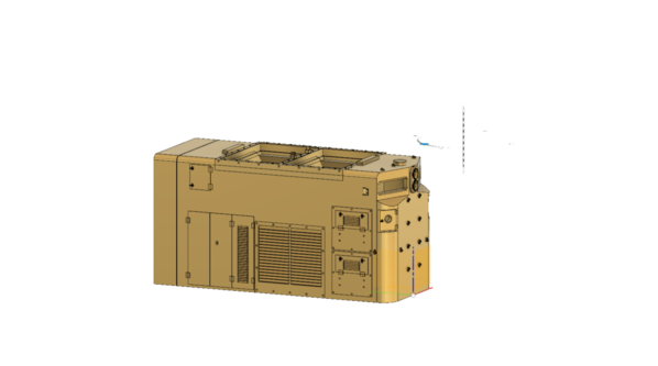
The design work is done in Autocad’s Fusion360.  This is free software, with limitations, for personal and business start-up use.  This is the drawing I made of the shortish hood (the C415 is somewhere between a center cab, and standard road diesel).    I colored it brass as I know a lot of you have a fetish for that material.   This drawing gets covered to a “mesh”, which is basically tens of thousands of interlaced triangles that follow the surfaces of the object.  The mesh file is an STL format, commonly used for 3d printing and CNC work.   The file is then loaded into a program called a “slicer” which came with my 3d printer.  The slicer is used to orient the object of optimal printing,  add supports, that keep the print in place, and are removed after, and to actually slice the object into .05 millimeter sections.  Each of these sections is a layer that is printed and then another layer added on top, and on and on.   This hood took 8hrs to print.  (You don’t need to watch, or monitor the printer).  The resin printer I used for this cost less than $250.

57A2971B-D22E-49BF-85A0-0D5215FD946807811D57-9C03-4D7D-BADA-E2339858FE91AA779482-E78E-445E-843D-90AB9992E4BD

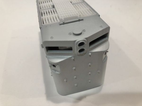
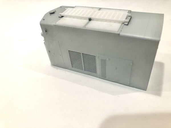
The radiator louvers and walkway on the hood top are laser cut, and they need some more adjustments to the design to make them a bit finer in detail.   This is the mostly raw print, with just a shot of primer to show what needs to be cleaned up.  The printer leaves some layering that can be removed with a half hour of careful sanding and a good sandable, filling primer.   The only things not printed, other than the louvers and walkway, are the wire grab irons, two lift rings on roof, and the door handles for long doors.  However, the nut/washer casting and start of holes are printed, and set up for Tichy drop wire grabs, and the plates for door handles are printed, but handles will be bent from wire and added.   Unlike the laser, the small wire holes tend to fill up with resin during the print and will need to be drilled out a bit, but at least they are started and locations set.  

I’m especially excited that the printer was able to print the flag holders on each side of hood side near the front top.  The hole for the holder is tiny - one inch at 1/48 scale.   The printer also did a good job with the small t handle latches on the small square doors on the nose and three on one side of the hood.    You will also see bolt heads around the side louvers and the radiator assembly.    These are roughly 1/2” bolt heads in real life.    

I still need to add the radiator louver actuators on the top of the hood, but I’m working on the long hood.  The long hood, although much longer, is actually simpler to draw, as it mostly just has a lot of the tall doors/hinges, and only a single louver on each side.   The roof is also very simple.  

Attachments

Images (4)
  • C1F253A9-351E-4C90-BA3F-5CD56FF664EE
  • 57A2971B-D22E-49BF-85A0-0D5215FD9468
  • 07811D57-9C03-4D7D-BADA-E2339858FE91
  • AA779482-E78E-445E-843D-90AB9992E4BD
Original Post

Replies sorted oldest to newest

@mark s posted:

Could this foretell a solution to the recent dearth  of O Scale brass imports?

Hopefully it will. I can see a lot of new models being produced out of resin, until the printable metal resins are becoming more affordable.

The transition should not be too difficult as most modern brass models currently produced are already designed in 3D CADCAM format. It should also allows a more friendly and less polluting process of fabrication, moving away from lost wax and high temperatures molding.

Yves

In reply to some of the above -

Chris - Yes, the limitations would be that there are learning curves involved with the 3d drafting software, and also with setting up the print.  

Jason - I wouldn’t worry about your age.  There are plenty of tutorials on YouTube that will help you learn.  Just watch them at the same time you have the program open.  Plenty of math will be involved so keep a calculator and pad handy.   Since almost all 3d printers function in the metric world, you will have to get familiar with millimeters, if you aren’t already.    Some people draw things to true world size and then reduce to scale, but I like drawing to 1/48.   The simple formula that gets used all the time is  -  inch measurement from prototype times 25.4 (converting to millimeters)  and divided by 48 (converting to o scale)   For this project, I also used plans from RMC that I scaled and printed at actual O Scale, and then just measured with a metric scale.   It’s nice having your son involved too - my son has three printers, and we both got into 3d printing together about 10 years ago, splitting the cost of our first kit printer (which is still functional and used)    It helps to have a partner when figuring out all the quirks of these machines and materials.  

Malcom - You are right about the hood, if would be daunting to scratchbuild those headlight angles.  Even with the CAD drawing, they were the hardest thing to work out.  It looks simple but you have multiple angles in different planes that intersect.  

Mark - Brass is sort of out of reach for me, partially because I’m a cheapskate, and partially because I just don’t know enough about all the manufactures, running characteristics, and fair prices.   But because the variety available in plastic is limited, building myself seems to be worthwhile to look into.  (And fun)   I build things in my day job, and we are sort of the go-to people for complicated and strange projects others won’t take on.  I like to challenge myself, even if I might fail in the end, which is still a possibility with this project.   This project is to essentially establish a template for building a locomotive.

  Figuring out a sort of universal chassis/drive, that can be modified for length and wheelbase easily, is the other aspect, of this project.  The fallback is to use P&D gearboxes and towers, but I’m also working on a dual motor, homemade China type drive, using 3d printed components and gearing.   It’s a bit complicated, but if I can get it all engineered right, functional, and to run reliably, it would lower the over all cost of  the locomotive significantly.   There might not be tremendous pulling power, but I’ll mostly be building switchers, and if power is needed, I could used the P&D hardware on larger road diesels.   My test will be if I can pull a dozen cars up our grade at the Cherry Valley club.  

Assuming everything works out with this locomotive(s)  (I’m building three versions of them - SP High Vis cab - Rock Island Standard Cab - and Monongahela Connecting  low industrial cab/ALCO Hi Adhesion trucks) , my next subjects would be a FM 10-44  and an EMD SW-1 .  

I will keep updating this thread as there is progress, but I’m also still building the G38/39 ore cars, and a few more DUNMORE Cabooses.  

OK, 'Oh Gawd' and/or snorting in disbelief time, but I have a vision of 3D home-printing filling the gap left when all the metal models disappear.  They'll disappear as the number of youngsters with metal-working skills shrinks, the number of companies producing intricate metal stuff shrinks and their products get more expensive.

While I'm fantasizing, lets dream about 3D printing (no, I haven't tried it yet).  It's already possible to create 3D models from drawings and/or with multiple scans (yes, copyright issues and expensive kit at the moment - hmmm, scanning businesses?).  3D software can be free and like all acquired skills just needs determination ... alright, an achievable target and some spare time.  3D printers have dropped amazingly in price already and can go in the spare bedroom. 

Maybe we'll have parts libraries available, some free, some chargeable, like internet music ... hey, I can put my 3D printer where that CD collection is.  No kids, I'll still keep some of those old LPs with the great covers.  OK, OK, I'll make sure the parts I'm upsizing from HO are slimmer where possible.

And then JM comes along and says 'keep up'.  Terrific!

No, I haven't even thought about metal-bearing resin.  Nearly all my stuff will be painted anyway, can I solder those difficult, leftover PSC parts to my basic printed piece.  How much is it with granulated nickel-silver resin?  OK, back to the internet.  Oh no, I've stumbled across the Transiting Exoplanet Survey Satellite (TESS).  They've found over 100 planets deemed to be worth investigating out there.  Maybe my Grandsons will need a great hobby when they have to do stuff like that for a day job.

Jason


7333F82F-AB2A-47F6-BD96-8D01A5224C4CD65EFCE4-2ECE-4A7B-82CC-C4429598BEB2C668A459-168E-4E2F-BFCA-ADC1FE7660CC

The C415 project got a little break while I worked on other 60s and 70s era freight car projects.  I will get into some of the other project at future dates on the forum, but I have managed to get back to the locomotive build.   The long hood cab work is underway.  Thankfully, the difficult part, the front of the hood, is just a copy of the short hood front, all that is left is to get off my butt and put in the many boring door details and I can print it.  I am slightly worried about the print, since it will be pushing the limits of size on my printer, and will have to be positioned almost completely vertical.    Originally I was going to make the cab from laser cut components, but then decided to 3d print, but since then I’m back on laser cutting, which I have done.   I might have to sacrifice some very minor details using the laser, however, I’m going this route as I want the cab wall thickness as close to prototype as possible so I can have a fully detailed cab interior.  With a resin printed part, I would have to leave a thicker wall, and probably some bracing, to prevent warpage.    As I said, the cab is laser cut and assembled.  The roof is a sub roof using 1.5mm acrylic, with the real roof a much thinner piece of sheet steel that I will replicate with either brass or styrene.   The chassis of this locomotive is a combination of 1.5mm and 3mm acrylic (1/8 and 1/16).   The prototype had some sort of longitudinal beams or stringers.  I am doing the same thing with acrylic in the hopes it will strengthen the whole assembly and keep things dead flat.  So far so good.  The fuel tank is also roughed out in acrylic.   The first version I am modeling, the Rock Island unit, had an extended fuel tank, which put both air tanks on the opposite side.  The SP and MonCon versions have standard fuel tanks with one air tank on each side.  

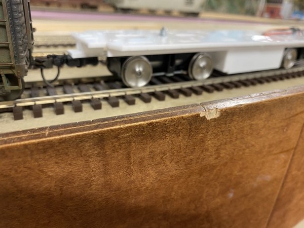
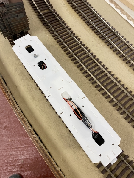
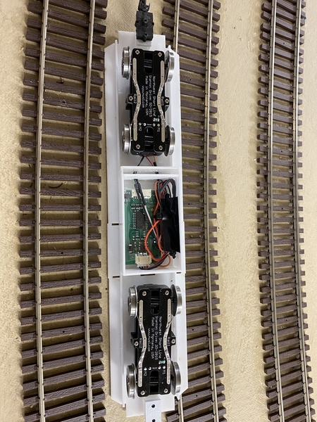
Drives - I didn’t really get any feedback on the Stanton Drive idea.  I guess no one uses these things?   I was having some space issues trying to arrange a motor with the short center cab, and thicker walled hoods, not to mention gear boxes and drive shafts, so I took a chance and ordered two Stanton units from NWSL.    They came fairly quickly, within two weeks of order, maybe less.   They are nicely built and wired, but almost immediately I realized that they are fairly tall, I guess to jam the motor and gears all into the truck.  I had thought I would need to build some sort of bolster for these to sit on, and the original frame was 1/4” acrylic.   Forget the bolster, and to achieve prototype deck-rail height, I would need to go to 1/8” (3mm) deck material.    The screws were a little tricky to work with that attached the trucks to the frame.  I wired in a decoder, located in the fuel tank, and brought it over last night to the Cherry Valley Club for a test run.  

Video of test -


It ran great.  Wonderful low speed performance and smooth.  Solo, the locomotive frame managed the steep grades we have at the club, however, with a half dozen cars, the wheels spun on the grades.  NWSL suggests a fair amount of weight for good traction.   Temporarily adding some weight, the loco handled the grades no problem.   The weight is something I will have to work out.  Also, don’t let the wiring fool you, I bought two powered trucks.  

Attachments

Images (3)
  • 7333F82F-AB2A-47F6-BD96-8D01A5224C4C
  • D65EFCE4-2ECE-4A7B-82CC-C4429598BEB2
  • C668A459-168E-4E2F-BFCA-ADC1FE7660CC
Videos (1)
F72140D1-D05F-44AE-A837-3381F1C73590

Add Reply

Post

OGR Publishing, Inc., 1310 Eastside Centre Ct, Suite 6, Mountain Home, AR 72653
800-980-OGRR (6477)
www.ogaugerr.com

×
×
×
×
Link copied to your clipboard.
×
×