
Okay guys

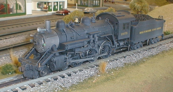
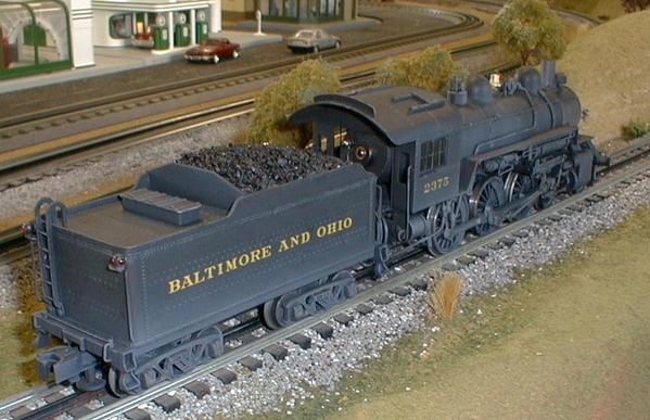
I imagine most of you who have been into this hobby for a while have had (or still have) this iconic model:

4-6-0

(eBay listing photo...)

I picked up an example this past week, and it should be here sometime in the future; while I wait for it's arrival, I would like to learn something about its construction and perhaps pick up a few pointers on what to look for.

The main driver on the opposite side is out of quarter, and it looks like some of the valve gear will need to be replaced; as per usual, any eBay engine I get will need to be disassembled, cleaned, etc...which leads me to my main question: how is the boiler/cab attached to the frame? Is it like similar-vintage HO, with a screw up through the cylinder block and maybe a couple under the cab? 

It's my understanding that this (and others) were owned by an outfit called "Babbitt": is that still a source? I'm not finding a whole lot of info on the 'web...

I appreciate in advance any and all comments and suggestions. 

Mark in Oregon

Attachments

Images (1)
  • 4-6-0
Last edited by Strummer
Original Post

Replies sorted oldest to newest

Feel free to ask.

The boiler may be attached as you say, or the screw may come down through the stack (unlikely) or once in a while the main screw will come up behind the cylinder block.  Two small screws in back.

Drivers are quartered mechanically, so you will have to use the glue trick.  Clean it up really good, then quarter it as well as you can.  Hold it in position and put some   shaft Loctite in there.  Tighten the nut, and let it sit for 24 hrs.

@bob2 posted:

Feel free to ask.

The boiler may be attached as you say, or the screw may come down through the stack (unlikely) or once in a while the main screw will come up behind the cylinder block.  Two small screws in back.

Drivers are quartered mechanically, so you will have to use the glue trick.  Clean it up really good, then quarter it as well as you can.  Hold it in position and put some   shaft Loctite in there.  Tighten the nut, and let it sit for 24 hrs.

Thank you for the helpful responses. I bet you've had a couple of these pass through your capable hands. 

Which color of Loctite should I get?

For some strange reason, I already have assembly instructions:

61016102

...but they were written for someone who obviously knows what they are doing, so that leaves me out! For example, I don't see any mention of how the boiler is attached to the frame...

As I say, it won't be here for a while, but rest assured I will no doubt have plenty of questions about this as I proceed. Am looking forward to this project...

Mark in Oregon

Attachments

Images (2)
  • 6101
  • 6102

Went looking for a photo for you.  Not only are they scarce as hen’s teeth, but also one site wiped out all of my bookmarks in one iPad.

Capture Al Stauffer’s B&O Steam book.  P. 227 is the best B-18 photo I could find.  Where is Bommer when we need him?

2024 is in green with gold leaf and red accents.  That’s the way I want to fix mine up.

Of all the All-Nation steam, this is the only one with a prototype.  The Pacific may come close to the USRA Light, but not with B&O drive wheels!

@bob2 posted:

1. Mine has a homemade frame.

2. But I can generally answer mechanical questions.

3. You need a photo of the B&O Ten-wheeler to guide your restoration.  I have seen spectacular examples - Joe Ferraioli did one.  I bet Ed Bommer did one, too.

1: Can we see it?

2: You can be sure I'll be asking  .  I'd like to look into putting a Pittman in there...

3. Will do some looking around; thanks again.

Mark in Oregon

On that ten-wheeler, the screw in the stack holds a bracket for the smoke box front.

To remove the boiler, first take off the engine truck up front. Then, the center screw that holds the cylinder casting to the boiler. After that removed the two screws holding the rear wall of the cab to the tailpiece on the frame. Then, carefully lift the boiler off the frame, taking  care not to yank out the headlight bulb wires.

The drivers were quartered by fitting into a machined square on each end of the axle that has a threaded extension on it.  A slotted nut-head secured the driver to the axle. To remove that head, cut a slot in the blade of a small blade screw driver. Keep it as an essential tool for working on a Varney/AN/Babbitt loco as all have the same quartering and driver attachment.

Having such a driver out of quarter means that it's either been forced, or was re-installed incorrectly  As the driver centers are cast brass and the axles are steel, it could be if forced the squareness of the driver's axle hole was compromised. 

A repair could be done as described, but the driver and axle set must be in the same exact quarter as all the others on the loco.  Not a simple thing to achieve without  a quartering jig set to match the original driver/axle setup.

Best to see if you can find a replacement driver. Not easy, but maybe not impossible.

Varney/AN/Babbitt drivers are all the same size, regardless of what loco they were on.  There were two types:  A main driver with a wide counter-weight and the secondary drivers all with a smaller same sized counter-weight.

Here's an All Nation Kit No. 5 Atlantic I built in 1970 at its new home in Rockford IL.  Scarcer than the ten-wheeler, it also was at heart a B&O locomotive!

BO1447b

Ed Bommer, aka here as S. Islander. 


,

Attachments

Images (1)
  • BO1447b: Not a ten-wheeler, but still an All Nation loco that used most of the same parts.

I should have added that if a driver was out of quarter, it could also be possible that the rod pin's holes in the rod ends have become elongated.  If they fit too loosely, the mechanism can bind even if all drivers are in quarter. 

Again, it might be possible to bore out elongated rod holes and refit them with brass tube bushings. But getting the rod pin holes to the exact spacing needed is a machinist's art. And, you have only one shot to get it right!   Replacement rods are another part not easily found now. 

FWIW: The special B&O P-7 class "Presidential" paint job of green with gold and red striping on B&O 2024 was for its status as the dedicated locomotive for B&O President Daniel Willard's inspection train from 1925 to about 1930. Depression era austerity put the 2024 back into pool service in black paint.  Willard's inspection train (usually a coach/baggage combine,  a diner, a 12 section /1 drawing room Pullman and B&O office car "Maryland") was from then on drawn by a pool service locomotive.

S. Islander  

Last edited by S. Islander

Okay gang, this old thing just arrived:

4-6-0 #1

It's not as bad as I thought: it looks like all I'm lacking is the main crankpin (#1531), nut (#1278) and whatever it is that keeps the eccentric rod in place. If anyone out there happens to have these items, in search of a good home, please let me know. 

4-6-0 #2

I think the body is held to the frame by (2) screws located under the pilot truck, and (2) more back under the cab. I don't see how else it's done.

The tender looks to be in fine shape, with nothing needed there...as far as I can tell.

I will begin the process of disassembly; just enough to test the motor, etc. Please feel free to chime in...

Thanks.

Mark in Oregon

Attachments

Images (2)
  • 4-6-0 #1
  • 4-6-0 #2

Thanks Bob; I appreciate the assistance.

After a couple of pleasant hours looking this over, I found a couple of things:

The motor was seized up tight; I gave it a "bath" in some WD40, worked it a bit, then cleaned everything and the motor now runs beautifully on about 4-5V.

460#4

If this the "slotted nut-head" mentioned earlier, it certainly will need to be attached, as it's now just kinda "floating" around and will fall out if you're not careful... 

460#3

I waited a long time to score one of these, and I'm in no big hurry to get it "road-worthy" (yeah, right!). As it is now, I think it makes a nice display piece. Looks much better without the huge motor in the cab:

460#7

I'm guessing this was not considered a "high end" model at the time, yet it really has nice details...

460#5460#6

46014602

All in all, a nice old model I think, for less than a hundred bucks... 

Mark in Oregon

Attachments

Images (7)
  • 460#4
  • 460#3
  • 460#7
  • 460#5
  • 460#6
  • 4601
  • 4602
Last edited by Strummer
@S. Islander posted:

1. On that ten-wheeler, the screw in the stack holds a bracket for the smoke box front.

2. To remove the boiler, first take off the engine truck up front. Then, the center screw that holds the cylinder casting to the boiler. After that removed the two screws holding the rear wall of the cab to the tailpiece on the frame. Then, carefully lift the boiler off the frame, taking  care not to yank out the headlight bulb wires.

3. The drivers were quartered by fitting into a machined square on each end of the axle that has a threaded extension on it.  A slotted nut-head secured the driver to the axle. To remove that head, cut a slot in the blade of a small blade screw driver. Keep it as an essential tool for working on a Varney/AN/Babbitt loco as all have the same quartering and driver attachment.

Ed Bommer, aka here as S. Islander. 

Ed 

Sorry for the delay in responding; thanks for all the good information.

1. You were right.

2. Also right; in my case, no headlight or wires to fuss with.

3. Good tip about the slotted screwdriver; will have to make one.

I contacted Bill at "BTS" this morning about possible availability of parts; he got back to me almost immediately. Said he'd dig around and try to come up with something. 

After I got the motor running, I attempted to put everything back the way it was; I had no luck in getting the motor with its large drive bracket to line up with the frame enough to be able to screw it all back together. What's the secret here?  

Mark in Oregon

Good news about Bill.  Couldn't tell what you were displaying as a "slotted nut" there.  Each axle gets two; you can see them in the center of the driver if the builder didn't putty them over.  That is where you want Loctite (and putty).

The main crankpin, as I recall, is held the same way, with a slotted nut, from the back side.  The eccentric is held in place with a small nail.  Being a little loose is not cause for alarm, unless the crankpin itself is loose.

Looks good - at $100 it is a true O Scale bargain.  Usually $250.

Mark and all,

The fit of the motor bracket is tricky. I loaned my All Nation steam loco instruction sheets a few moths ago to someone who wanted to make a copy of them. But they've not come back.   I will try to recall. I sold my 4-4-2  two years ago, so I  no longer have a ready reference.

The bracket has a horseshoe-like end which attaches to the motor with a pair of 4-40 round head machine screws.  The holes in the bracket I had were a little oversized, which allowed for some wiggle room in adjusting the fit of the motor. I think there were motor bracket tail end mounting screws too.

The other end of the bracket has a toe-like extension with one (?) hole in it for another 4-40 (or 6-32) machine screw to hold it to the fame. That end is where you adjust the mesh of the worm and drive gear on the axle, with a thin washer or two under the toe.  The drive gear mesh needs to be about 50% into the worm so that its a good fit, but not loose enough to have any gear tooth backlash. Nor so tight that it binds at any point when the worm shaft is turned by hand. Once that is set the other screws holding the motor bracket to the fame can be tightened, then check the gear mesh again. 

It's a fussy job to get it right, but once set correctly. that drive can outlast us all. It reminded me in part on how a mechanic sets the mesh of a pinion and ring gear in repairing an automobile's rear axle, but those days are gone now. 

Now here is where I need to see an instruction sheet, because I'm fuzzy on just where the motor bracket toe meets the fame. Is it on one of the round spacers holding the fame sides together, or does it reach down to the bottom plate that holds the driver bearings in place? 

Either way, the fit of that motor bracket toe screw also determines how far back or forward the motor and bracket will be on the frame. On the 4-6-0, the bracket toe screw hole should be in front of the middle, main driver axle, to center the worm over the main driver's gear. Be sure to check the worm to drive gear mesh.

Onward!

S. Islander


Thanks guys

Bob: that picture was supposed to show the "slotted nut" that holds the crankpin: (the crankpin is one of the missing parts, along with the eccentric crank itself and whatever it is that holds the eccentric rod to the crank...you say it's a small nail?) I'm hoping "BTS" Bill will find some. I guess I should feel lucky that the slotted nut was still there, since there is really nothing to hold it in place. I've currently got a long 2-56 bolt-head screw holding everything together for the time being, just so the side rods don't flop around.

Ed: indeed, the front end of that bracket is supposed to reach down and connect with the bottom plate. I fussed with that for quite a while yesterday and just couldn't get it right. I suppose there's no point in worrying about that until I can get those valve gear parts anyway...

As I look further into this, it's amazing how almost everything is held together with screws...of all different sizes. Heck, even the marker lights on the smokebox front are screwed to their brackets...which are in turn screwed to the smokebox front. The steps on the pilot: screwed in place. The tender hatch: 2 screws; tender steps...and on and on...

One last thing: from the underside, the boiler looks like one big hunk of...bronze, maybe? I took the smokestack off to adjust the smokebox front, and that unpainted section of the boiler had a reddish tint...

Very cool old model!

Mark in Oregon

@bob2 posted:

1. Yes. Sand cast brass or bronze.  I think the exact alloy was whatever they were pouring that day.  2. Let us know if Bill doesn't find your parts.

1. Thanks Bob.  This thing has a wonderful "old school" feel to it which I find most compelling; can only guess that's something like what Carey Williams must feel when he plays with his fantastic collection of old stuff...or any of you with your Lobaugh, Hines, etc.

2. I will keep you all in the loop regarding "your parts"... 

Mark in Oregon

I spent a few more hours fussing with this, and this is what I discovered.

My All Nation instruction sheets show that the big u-shaped bracket is closest to the motor; with the "mounting foot" outside of it:

622623

However, on this Varney example (which has a different motor), the "foot" is up against the motor, with the big bracket outside of it:

6:20

Once I figured that out, it all came together fairly easily. Note that there are (2) tapped holes in the "foot", so one wonders is there was a modification made at some point. Odd thing is that I now have an extra brass washer; where that came from is a mystery.

washer

It is perfectly sized to fit on the worm shaft, but upon installing it, it was too tight and bound up the mechanism. 

As it stands now; given the fact that it's missing several crucial pieces, it runs very well up on blocks. Am hoping that BTS can come through with those parts: (in the meantime, I am open to any suggestions and/or offers... &nbsp

Mark in Oregon

EDIT: By swapping the 2 brackets back to where they should be, we gained enough space on the worm shaft to put that washer back where it belongs...🙂


Attachments

Images (4)
  • 622
  • 623
  • 6:20
  • washer
Last edited by Strummer

Update:

Thanks to a fellow Forum member (who I shall not name, as I didn't ask permission to do so), the much needed valve gear parts arrived today. Now on to the questions/problems...

How exactly does one set the "timing" on the main crank?

That may be a moot point however, as I think I have discovered a real issue. It looks like the left side "valve rod" has seized up in the cylinder, and it is no longer connected to the "combination lever". Because of this, that "combo" lever cannot swing freely enough and is causing a bind. I tried to take a couple of photos:

62916292

These don't really show much; I just wanted to illustrate the "where" as much as the "what". You may notice I have disconnected the (according to Wikipedia) "union link" so that at least the rest of the gear can move...

Because the instruction sheets are so vague, I have no clue as to how to take this apart enough to try to fix it, and due to my ignorance about this kind of stuff, I think I may be "dead in the water" with this.  

Your thoughts are not only appreciated, but needed!   

Thank you.

Mark in Oregon

Attachments

Images (2)
  • 6291
  • 6292
@bob2 posted:

Remove the combination lever and anything that is attached to it.  The radius rod may not be riveted to the Walschaerts link, and may just slide out.  Then clean it up and re-fit.

instead of WD-40, try acetone or lacquer thinner, just in case it is all welded with paint.

Thanks bob2 (the guy who sent me those parts.)  

Maybe this is why I was able to get this for only 75 bucks... 

I'm just unsure as to how this was all put together: the top of the combination lever (where it is hinged, I suppose) is tucked up inside that part of the cylinder (as in my photos), so I can't actually see "what goes where". I hate to be a PITA, but I obviously don't wanna make things worse...

Mark in Oregon

Yes.  The eccentric is canted slightly forward with the rods bottom dead center.  Adjust those main crank pins that way, then Loctite, then driver on axle w/ Loctite. Final step is pinning the eccentric after the rods are back on.

Radius rod does not need to be pinned to the Walschaerts link, but there should be a pin to keep it from sliding too far aft and allowing the valve stem to fall out of its guide.

Spanner driver is what you use on those types of nuts/screws. They also have dot versions with holes vs slots... pig nose, snake eye, dot, spanner, varies by maker what they call them.

The dot type work on slots, but not visa versa. Many, even cheap, tamper proof bit sets have them (usually the slotted version)   You can find precision sets too though.

There are large spanner wrenches and socket sets for industry.

And side noteInote ItI they call an open end wrench 🔧 a spanner in the UK I think. (goofle spellwreck, not my fault)

This locomotive kit has a long history in O scale.    As I remember it was originally issued by Varney.    Then a company called General Models bought the models and patterns and it was issued by them for awhile.    After that, The All Nation hobby shop bought the line and it became All Nation for years.    I am most familiar with that line and they had at that point in 70s the 4-6-0, a 4-4-2, a 4-4-0, and a 2-6-2.    They also had F3 and F7 A and B Units along with the NW2 switcher.    I think the diesels were added when is was General Models and some of the steamers.    There has also been an 4-8-2 and an articulated of some type mentioned as part of this line.

All Nation sold off the Steam loco line to Babbitt who made a lot of upgrades to the mechanisms which included sprung drivers and I think Can motors.     Finally Babbitt sold the steam model line to BTS, Bill's Train Shop.

I don't know the dates for these changes.   When I got in the hobby it was All Nation and it was a big player in the O Scale hobby at the time.    Also, all models were not always available at the same time.     It would be interesting to learn when each model was added to the line.   They do all follow similar assembly and have a family look.   Also, they all used the same size drivers.


prrjim:

I agree.

Another question: The 0-80 brass bolt that holds the eccentric rod to the main crank:

6303

...if I tighten this up all the way, it binds. If I loosen it (just enough to allow it to function), won't it continue to loosen itself until it drops out and I loose it forever?  Is this where some Locktite comes into play?

More fun and games... 

Mark in Oregon

Attachments

Images (1)
  • 6303

Yes, Loctite should work OK. But be sparing! There is little drag on that screw from the rod.

Like all machinery that goes back 60+ years or so, model locomotives likewise needed regular inspections to check on loosening screws (especially on steam locos and cars with machine screw king pins), any need for cleaning wheel treads and if needed, some oil or grease. 

Regular maintenance gives a longer, more trouble free life whether its a car, truck, bus, boat, locomotive or operating model.  However, older things needed more care. Older operating models, likewise. Gone are the days of the 1,000 mile grease job and oil change for a car or light truck, also the 30,000-40,000 mile "carbon and valve" job! 

Been there, done that, S.  Islander

That nut for the eccentric might be a replacement for the original.   Is it possible that there was a shouldered nut or screw at one time?    Are the eccentric holes a little sloppy on the bolt?

Well even if that is the original construction, a shouldered bolt would solve the problem, and you could make one with the existing bolt.    Simply find a piece of brass tubing with an ID the same (actually a couple 1000ths inch bigger) as the OD of the bolt shaft.    Cut a length just a few thousandths longer than the thickness of the eccentric rod.    Slide it over the bolt and then install the bolt.    You should be able to tighten the bolt down while the eccentric rod rides on the piece of brass tube.    some guys solder the piece of tube to the bolt, some don't.   

Now if it originally had a shouldered bolt, the tube should fit the hole.    If not,  you may need to bore out the hole a little if there is enough material.  

A friend of mine made shouldered scews and bolts like this for many of his HO locos which are much tinier and fiddlier.

Thanks guys. 

As it turns out, I tried something a bit different and it seems to be working:

The 0-80 bolt I got from bob2 is 3/32" in length over all. Since there was no "play" if I tightened it all the way, I thought maybe a slightly longer bolt would do the trick. I shortened a different 0-80 down to 1/4". That extra 1/16" made all the difference; I can now tighten the bolt fully (so it stays tight) yet there is a little "play" for the eccentric rod to move freely.

The chassis is now (more or less) reassembled and is turning at a nice 3V; will kick in at 2V off my Heathkit power pack (which is a whole other story). Still need to put it on a track, but I'm feeling pretty good about this project right now... 

Question: the tender has no rivet detail; is as smooth as can be. Can that be right?

Mark in Oregon


It is just the way its made.  A fairly heavy sheet brass wrap around for the walls, that would defy putting in rivet impressions. It was a lower cost kit at the time and the lack of rivet detail was largely overlooked.  Other, more expensive kits of the day with brass sides having rivet impressions used thinner material or they used aluminum castings with details molded in. All Nation had them for its larger locomotive kits.

On my All Nation 4-4-2, I made a thin shim brass sheet of rivet impressions to apply to the smooth brass sides.  It was labor intensive to be sure. I wanted to put rivet detail on cab as well, but after working on the tender, I though otherwise.

If I were to do this now, I would apply primer to the smooth brass tender shell and apply rivet decals, following the prototype pattern from photos.  Rivet decals will bond better to primer or paint than they will on plain brass.

S. Islander  

Attachments

Images (1)
  • TRAIN 23: All Nation B&O 4-4-2 at Edgewater with a branch line local.

Okay gang, I need some "fine tuning" tips here.

When this is up on blocks, and running in reverse, it runs perfectly. Here is a picture how how the worm sits when in "reverse" mode:

gear 1

You can see there's just a very slight gap between the brass frame and the washer/worm. The entire shaft: worm, armature, etc. turns smoothly with almost zero fore and aft movement. Perfect. 

Here is the gap when polarity is reversed, for running "forward":

gear 2

Although not much greater, I think that gap is now enough to throw the worm too far back towards the rear of the engine; this (I think) is what's causing a "hitch" (both visible and audible) in the mechanism. The shaft now moves fore and aft by as much as a 32nd(?)

I cannot detect any other reason for this "hitch". I don't think that adding a very thin additional washer would help, as that would cause a bind when in reverse...maybe. 

There is not a whole lot of adjustments available with the way this is designed; I thought that maybe I could tweek the big brass "arm", and maybe move everything slightly forward, but I just don't see how that could done, and even then help much.

Speaking of "help":..HELP!  

Mark in Oregon

Attachments

Images (2)
  • gear 1
  • gear 2
@PRR1950 posted:

Back on page 1 of this thread, you had an "extra" washer after you put the engine motor back together.  Think that might have anything to do with this problem?

Chuck

Chuck

Later in the discussion (still on page 1: I count the 26th post) you might see I discovered that once I put the mounting "plates" in the correct order, I was able to put that washer back where it was: between the large "U shaped" brass bracket and the worm. I added the information as a "PS" to that post.

I just seem to have too much fore and aft play, and I THINK that's where my problem is. The worm is free to move too far back towards the rear of the engine, and the mesh between it and the main drive gear gets "out of whack".  I think that's what's going on, but I can't be 100% positive, as this is my first O scale loco of this type...and again, I only see this issue when it's running "forward"...naturally!   

Mark in Oregon

Last edited by Strummer

True dat...yet I don't see any access "slop" in the motor or commutator. And again, it runs beautifully in the opposite direction (reverse): smooth as silk. Very puzzling.

I wonder if the big brass "coupling" that ties the motor and worm shafts together: is there perhaps any way to adjust that? Since this came to me already assembled, I don't know how all this was put together... 

Mark in Oregon

Yet another (in a long line of annoying) updates:

Since I couldn't fathom how to reduce the "play" in the driveline itself, I figured my only other option was to try to adjust the mesh between the worm and gear.

Since this is assembled in more or less sequence, it wasn't easy to do. I removed the bracket's front mounting screw, the (2) screws that hold the motor to the mounting brackets, and then loosened the longer rear mounting screw. This gave me enough wiggle room (yet still held everything in place) to add a thin (1/64") washer between the frame and the front "foot" of the bracket, nearest the worm. In the photo the screwdriver is pointing to the area I'm referring to:

Hooked up a couple of leads, and PRESTO! I think that worked! It now runs equally smooth and quietly in both directions: so quiet, in fact, that I have to lean in close to be able to hear any sound at all. Of course, it's not all reassembled and on the test track yet, but I'm hopeful.

There was at one time a discussion on the "Model Train Journal" forum about this model and a similar fix was suggested. I don't know what that outcome was, but my All Nation instructions don't show or mention any "spacers" to be used at this spot...

Anyway, there you go...for now. 

Mark in Oregon

Attachments

Images (1)
  • 6141
Last edited by Strummer

Jonathan

Here's hoping you do someday find one; a completely "new" and un-built kit would no doubt be better than the one I've been dealing with here.

This Varney example is still showing signs of an occasional bind: I had it on the test track today, and although it runs okay for a while, it'll suddenly seize up and the "overload" light on my Heathkit power supply will come on. It looks to be the center (geared) driver on the left (fireman's) side; a little gentle rocking will free it up again, but this happens repeatedly, so I guess I'm not out of the woods yet!

I enjoy the whole trouble-shooting process (and discussing it here) but this engine is really putting me to the test...

Mark in Oregon

I am going to post three of my Harriman ten wheelers.  I have four, all in 17/64 scale.  The first is a T-31, with 69" drivers and a tiny heart pump motor in the firebox.  It can pull maybe four cars.  The other three are tender drive, and they can pull anything they can hook to.  You can see the narrow firebox quite well in all my photos - ten wheelers in general are not well suited to in-boiler motors.  You should see what PSC had to do with their gorgeous, but fragile, T-28.

I may have the SP designations wrong - now and then I look them up - but T-28 is a 63" drivered all purpose locomotive, and some had Walschaerts gear, but not all.  The archetype is Varney's HO ten-wheeler, which is sort of Harriman, but with a wider firebox.  Herewith:

235523532348

Attachments

Images (3)
  • 2355
  • 2353
  • 2348

I should add that 2355 - the real one - is a T-28, living in a park in Mesa, Arizona.  2353 was within walking distance of the Imperial, Ca. airport until the 1980s or so, then came to San Diego to be resurrected to full operation for a couple years on the old SDAE trackage.  It had a museum logo where I placed the SP logo on the tender, and had been fitted with a tender pilot.

2348 features some square counterweight drivers, making it incorrect in almost as big a way as the 2355 - but I don't care.  I like those drivers.  I had to make tires for all of them, but I think they were Max Gray.  The last one, not shown, is a bit more accurate, with Sunset drivers and Stevenson valve gear.

One of the guys on another forum suggested that ego might be involved in posting photos of one's own work.  I certainly resemble that remark, and make no apologies.  However, I love to see others' work, so I figure posting my own will cause others to share - there are already some pretty spectacular models in this thread.  Let us see your ten-wheelers?

Magnificent, all 3.

European steamers have often featured "tender drive", but that usually means the tender is powered and driven. You see HO scale tender drives, but the shaft going to the engine is often up at about the mid-way point.  Yours have the driveshaft so low they are barely seen...terrific! It really helps the look when you have all that open space between drivers, frame and boiler...

Mark in Oregon 

I've been under the assumption that my example is a Varney; given the fact that several parts are stamped/cast with that name. However...

...Don's post from 7/1 shows the All Nation 5/8" stack motor (made by Pittman), used on "...the Diesel Switcher, Atlantic and Ten Wheeler locomotives":

motor #2

I thought that was the motor mine has:

motor

...except I just measured mine, and it is the full 1" stack motor; no wonder it sticks out the back of the cab so far! But in any case, it is an All Nation/Pittman. So I suppose after All Nation took over the Varney line, parts from both makers could have been thrown into the same kit box...

Also, my instruction sheet (dated 12/14/46) shows a field-wound (?) motor:

motor #3

...and shows how to wire a "reversing switch" for that type of motor.

One wonders went the change over to the permanent magnet motor took place; any guesses?

Mark in Oregon

PS: If anyone has a decent 5/8" stack motor they'd like to get rid of, please let me know. I'd like to try one on this model...


Attachments

Images (3)
  • motor
  • motor #3
  • motor #2
@scale rail posted:

1.  Stummer, glad you could get some info from my catalog. Let me know if there would be any other stuff you could use.

2. Love this thread, it's real modeling to me. Don

Don

1: Glad it was okay for me to re-post your catalog page. Thanks for posting it in the first place; and by all means, feel free to put up whatever you've got! 

2: Thanks. Sometimes I think I enjoy the posting of the project (almost) as much as the project itself... 

Now if I can just find one of those 5/8" stack motors...(hint, hint...)  

Mark (still) in Oregon

Don't get too hung up on what shows inside the cab.  These are primitive models, compared to the state of the art.  Maybe a Faulhaber motor would be smaller.  The narrow firebox locomotives typically had the cab pretty much astride the firebox - the fireman had to walk back to the tender apron to visit the engineer.

So here is a Saginaw ten-wheeler, patiently awaiting a new firebox, valve gear, and reversing bridge:

Saginaw 001

Attachments

Images (1)
  • Saginaw 001
@bob2 posted:

Wow!  My photos can kill a good thread in a heartbeat.

Funny...nice Saginaw engine.

I've been running the topic subject Ten Wheeler as time allows; still needs a tweak or two. I've applied loktite to a couple of driver screws that managed to work themselves loose, and am starting to think that the rear driver on the fireman's side is a little cocked on its axle: it looks like its rotation may be a little off, as the engine has a sight "shimmy" when going through curves. Not terrible, but noticeable. Other than that, it seems to run well. It makes a lovely "solid" kind of sound when it's running. You hear that same sound (only more so) on Carey's videos; old school stuff...

Mark in Oregon 


Mark asked about the Baldwin 60000 mechanism in another thread.  Since my mechanisms are only suited for O Scale, I decided it best to respond here.  Three shots of the giant Baldwin mechanism follow, for Mark, and to stay within the spirit of this thread, I will include a tender drive "ten-wheeler" mechanism.


O Scale Trains 010O Scale Trains 011O Scale Trains 012gears 007

Attachments

Images (4)
  • O Scale Trains 010
  • O Scale Trains 011
  • O Scale Trains 012
  • gears 007
@bob2 posted:

Don't get too hung up on what shows inside the cab.  These are primitive models, compared to the state of the art.  

Good advise, that. I should have listened!

Not to leave well enough alone, I purchased this field-wound motor to give it a try:

729

Unlike the DC motor (with a 1" stack that came with this engine), this motor is only 5/8" and I thought it might "disappear" into the cab, so away I went.

The hardest thing to do was to remove the big brass coupling from the worm shaft: it's held in place with some kind of spring steel pins, and they were a real bear to pull out. Eventually I got it free and used a length of aquarium(?) tubing as a new coupling (you can see this in the photo.)

The mechanism came together nicely, checked out well on the bench; but when the time came to reassemble everything, the field coil was too far forward and too tall; it interfered with the boiler/cab. You can see in the picture where I trimmed a little of the bakelite(?) insulators, but it was a no-go after all.  

Strangely enough, when I put everything back the way had been, it seems to run better now; I think that the brass coupling now has the tiniest bit of "play" in it, so it's not as rigid as before and is a smoother fit. Is this even possible?  

Anyway, there you have it. I'm not going to re-finish/re-paint this model, as I really like the original patina, and it's in pretty good condition anyway.  

This has been a very enjoyable project; I wasn't sure if this would ever be anything more than a display piece, but thanks to all of you I have learned a lot about the mechanics of old O scale, and now have even more fondness for these old models...

Mark in Oregon


Attachments

Images (1)
  • 729
@bob2 posted:

I looked your home city up - just north of Astoria?  What a beautiful place to live.

Don't give up - how about some photos of your other O Scale?

Actually, where I live is the Central Coast; Astoria is well north; the last place before the Columbia River and Washington. And yes, it's very beautiful; I feel fortunate to be able to live here.

Certainly not "giving up"; just wrapping up this project. It's currently running really well. Which reminds me of a question I have been meaning to ask: when you guys run your older models, what sort of power source do you use? 

Mark in Oregon 

I use a 120-24 volt step-down fed by a Variac.  Output goes through a $2 Radio Shack bridge rectifier and a DPDT switch.

I have circuit breakers on the 120 volt input and the DC output.  A red light tells me I left it on (had to do that on my soldering iron, too), and an ammeter and voltmeter round it all out.

I also have a giant electrolytic capacitor across the output of the rectifier - probably not necessary.

While not locomotives, I have some kit built O scale models that are about as old as I am or more. 

These two are older than I am. The Scale Model Railways C&O box car from 1937 is numbered for similar type AAR boxcars C&O used for post WW-II auto parts shipments. They were fitted with special racks to haul engines, rear axle assemblies or automatic transmissions to assembly plants.  A friend sent me five aluminum castings (two ends, two sides and a roof) which made the body in 2000. I scratch made a floor and put on full underbody detail.

The Lehigh Valley hopper is  a rebuild of a Scale Craft kit OF-134 from 1936, found on E-bay in 1999. I didn't get to work on it until 2017.  It is also made up of several cast aluminum parts.  Today, epoxy makes building (and rebuilding) these old models a lot easier than it was in the 1930's. Back then, you drilled and tapped the parts for screws, whose heads had to be countersunk and hidden with putty before painting, or drill holes to drive in brass pins. An Intermountain coal load made for their plastic USRA hoppers fit this 84 YO piece perfectly.

In the 1930's, cast aluminum was widely used in making model train kits for freight and passenger cars. Some could turn out quite heavy, especially Mi Loco cast aluminum Pullman cars.  Hauling trains with those cars in them required a big motor which could also quite a juice hog. 

Also added are two more kit built cast aluminum cars: a 40' Scale Craft stock car from 1939 that well models a T&P car of that time. Also Walthers' 12 wheel cast aluminum, depressed center flatcar from 1940.  With wide-spread rural electrification programs being done during the 1930's, cars like these shipped hydro-power generators and transformers from eastern factories to where generating plants and power distribution networks were being built. 

S. Islander

Attachments

Images (4)
  • 127: Scale Model Railways cast aluminum boxcar from 1937. Some of these were run on the American Railroads layout at the 1939/40 New York World's Fair.
  • 188b: Scale Craft cast aluminum kit OF-134 of 1936, modeling a USRA two bay hopper.
  • 163XBC: Scale Craft aluminum kit of 1939
  • 187 S: Walthers aluminum kit from 1940. Was still available in the 1960's.

Very nice; thanks for showing those.

This is pretty much all the "older" stuff I have at this time:

861

...just some Athearn cars, that brass hopper (which you all identified as US Hobbies), the Walthers N5 caboose (no, it's a "cabin car!") and lastly...my scratch-built caboose. It's not "vintage" (only 25 years old), but it does have vintage Lobaugh trucks...does that count?  

Mark in Oregon

Attachments

Images (1)
  • 861

Hello again. 

Back on the first day of this month, I posted that I was probably done with this thread "until something else breaks and I need help again". Guess what? 

This has been running beautifully; except every now and then it'll seize up and stop. I had it apart (again) this morning: the motor/driveline checks out OK, and the chassis sans motor rolls free and easy. If I attach the motor/driveline, it'll run fine up on blocks, but once it's on the rails and has to propel itself, it will freeze up again.

I think the problem has to do with the center geared drivers. There is a little "play" in the front and rear set, and if I move the center set on the engineer side, it is the same. On the fireman's (left) side, there is none of that play; I think my issue is that one of these drivers (probably this one) is not "seated" properly on the axle. I'm guessing I'm going to have to drop that axle assembly out of the chassis and re-do the driver/axle connection.

 I did not do the initial building of this engine, and don't really know how it was supposed to be assembled, or what to look for, so fixing it might prove to be bit of a challenge. Any ideas/suggestions would be greatly appreciated.

Thanks yet again.  

Mark in Oregon

"Quarter" is your problem.  All drivers must have crankpins at the same angle - usually 90 degrees or thereabouts.

Pull the rods off, set one side at top or bottom dead center, and make sure the other side is in a very straight line - in line with the axle centerlines.  A loose driver can be fixed at this point with Loctite and your special screwdriver.

To hold the drivers at top/bottom dead center, you can drill an aluminum plate with tight-fitting holes - spacing must be exactly the same as axle spacing.  If the rods are tight (unlikely) they can be used.

Then the rods must be re-fitted after the Loctite sets.  You fit them at front and back dead center.  You will see interference if there is any - the rod must be adjusted so there is no resistance.  Use a magnifying glass, and pins without caps. You may have to make test pins.

@scale rail posted:

Strummer, 

1: did any of those motors work out for you that were on E-bay?

2: By the way I remember crossing the Columbia River on the Maryhill ferry when I was a kid. It was just a barge you drove on and a little tug boat pulled it across the river. 

1. If you read the first post at the top of this (the 3rd) page, you will see how it turned (or not) out. 

2. Cool memory; by the time I moved here (1975) the big Astoria Bridge was in place and the barge was gone.

Mark in Oregon

@bob2 posted:

"Quarter" is your problem.  All drivers must have crankpins at the same angle - usually 90 degrees or thereabouts.

Pull the rods off, set one side at top or bottom dead center, and make sure the other side is in a very straight line - in line with the axle centerlines.  A loose driver can be fixed at this point with Loctite and your special screwdriver.

To hold the drivers at top/bottom dead center, you can drill an aluminum plate with tight-fitting holes - spacing must be exactly the same as axle spacing.  If the rods are tight (unlikely) they can be used.

Then the rods must be re-fitted after the Loctite sets.  You fit them at front and back dead center.  You will see interference if there is any - the rod must be adjusted so there is no resistance.  Use a magnifying glass, and pins without caps. You may have to make test pins.

Thanks Bob; sounds like this is what I'll have to do. A couple questions:

1. can you explain what you mean by "axle centerlines"?

2. "...front and back dead center"?

3. What do you mean by "pins", and what are these used for?

Please forgive the elementary questions, but I've never had to quarter a steam locomotive before...believe it or not! 

Appreciate the assistance...

Mark in Oregon


Axle centerlines - the axle is a dowel or cylinder.  Picture a very small hole drilled right through the center, from side to side.  Centerline goes right through that hole.

I often center-drill my axles, but tough to do on All Nation.

Top, bottom, front, and back dead center - crankpins up, down, forward or back.  And "dead center" is a term of art - it is that point where the crankpin is as far up, etc., as it is possible to go.

On a driver, it is easier to just eyeball it.  An aircraft engine gets a little whisker in the sparkplug hole that actuates a lever on a scale.

I use "pins" as shorthand for "crankpins" which, in your case, are the little screws that hold the siderods on.  In a car or aircraft engine, the crankpin is that part of the crankshaft where the rods bolt on.

you will need to find threaded pins without the head if you need to investigate siderod bind after quartering is done.

You are on a very steep learning curve.  It took me months of experimentation to understand all the little problems that can be associated with steam engine rods and drivers.

@bob2 posted:

Axle centerlines - the axle is a dowel or cylinder.  Picture a very small hole drilled right through the center, from side to side.  Centerline goes right through that hole.

I often center-drill my axles, but tough to do on All Nation.

Top, bottom, front, and back dead center - crankpins up, down, forward or back.  And "dead center" is a term of art - it is that point where the crankpin is as far up, etc., as it is possible to go.

On a driver, it is easier to just eyeball it.  An aircraft engine gets a little whisker in the sparkplug hole that actuates a lever on a scale.

I use "pins" as shorthand for "crankpins" which, in your case, are the little screws that hold the siderods on.  In a car or aircraft engine, the crankpin is that part of the crankshaft where the rods bolt on.

you will need to find threaded pins without the head if you need to investigate siderod bind after quartering is done.

You are on a very steep learning curve.  It took me months of experimentation to understand all the little problems that can be associated with steam engine rods and drivers.

Omigod... 

Before I start tearing things apart, here is where we stand as of right now:

82718272

My crappy cell phone distorts the image a little; but it looks "close", doesn't it?

Something else (which I'm sure is partially to blame): the first and third (non-geared) wheels are tight on their axles: no play, so if you wiggle one driver, the opposite side moves the same amount.

The center axle shows play between the (2) drive wheels; you can actually move them (ever so slightly, to be sure) in opposite directions! And again, the driver in the second picture shows no axle/wheel "play"; the opposite side (first photo) there is a bit of "slop" with that center wheel. I thought I had fixed that before, but apparently not...

I have built HO scale steam loco kits and have had to "build" all this, with success; in a model of this size and weight, it appears there are real "physics" involved here... 

Mark in Oregon

Attachments

Images (2)
  • 8271
  • 8272

Bob, et al.

Okay, I've taken this down; dropped the main driver, pulled the (slightly) loose one, cleaned the heck out of it, reassembled with (blue) Loctite, and now we wait 24 hours...

8291

This is good; it helps to see how this was put together. I was never quite clear on the whole "keyed driver" thing, but now, having seen it first hand, I get it. 

Mark in Oregon


Attachments

Images (1)
  • 8291

Add Reply

Post

OGR Publishing, Inc., 1310 Eastside Centre Ct, Suite 6, Mountain Home, AR 72653
800-980-OGRR (6477)
www.ogaugerr.com

×
×
×
×
Link copied to your clipboard.
×
×