Twenty seven years ago, on my son's 2nd birthday, we started collecting trains with the intention of having a permanent layout in the basement.  But, raising a family, working full time to support them, and moving 3 times all got in the way.  Finally getting around to make some progress on the permanent layout goal.  Late start probably kept me from some expensive mistakes, as our criteria evolved significantly along the way.  Rather than stuffing as much track into every square inch, I think we would be happier with a reasonable and realistic mix of track, structures, and scenery.  Working with some significant area limitations, and literally several hundred versions of the track plan later, off we go.

The lower track will be a folded dogbone of working track to operate (lot of switching, everything within easy reach), with an upper track around the perimeter to just run trains.  Still working on the storyline, but basically the lower is a branch line serving local industries, while the upper is a two track mainline connecting the local to the world.  One of the compromises I had to make was eliminating the grade connecting the two levels.  With a realistic 2%, an 8" rise required over 33' of dedicated track, which would have taken a significant amount of real estate better utilized for other purposes in my little room.  So we decided to simulate the interchange, with the offsetting gain more industry along the lower track itself.  

Big thank you to members of the forum, a great learning tool and resource for us newbies.

Screen Shot 2022-04-30 at 3.27.46 PM

Attachments

Images (1)
  • Screen Shot 2022-04-30 at 3.27.46 PM
Last edited by Sather
Original Post

Replies sorted oldest to newest

Since I am using sectional track, I just used trusty old MacPaint as track planning software.  As plywood was added on lower level benchwork, I started placing items on it to get a feel where and how things would fit.  This helped immensely, as I found I was able to keep O-54 as the minimum radius on the lower, on the two dogbone ends.  (O-72 is planned as a minimum on the upper, to accommodate cars that need bigger turn radii.)  The downside is, the ensuing clutter has to be moved multiple times as I move around on the tables to work on the perimeter.  

LOVO4872

Attachments

Images (1)
  • LOVO4872

Once the lower plywood was fully installed, I placed the whole lower track, hooked up wires, and ran it for a few weeks to verify reliability.  Also, first chance to fire up the MTH DCS, which has been sitting on boxes in the hall drawers for a decade.  (Warranty long expired, luckily it worked.)

IMG_5028IMG_6747

Attachments

Images (2)
  • IMG_5028
  • IMG_6747
Videos (1)
IMG_5213
Last edited by Sather

With the lower track roughly in place, I can start work on the upper benchwork.  Previously installed a 1" x 2" on the perimeter wall, so just need supports in a few appropriate places deconflicted with the lower track.  Where tunnels will be, preserved access through the lower plywood.

DBSH7844IMG_6900 IMG_6903

Attachments

Images (3)
  • DBSH7844
  • IMG_6900
  • IMG_6903
Last edited by Sather

Thanks.  It is a combination, mostly depending on what I had laying around from other projects.  The framing is primarily 1" x 4" Poplar, with a few specific pieces ripped (to the same dimensions) from Baltic Birch plywood where needed for added strength.  (The posts and long beams the joists sit on, for example.)   The table top is just regular Birch ply to keep the costs manageable, as I expected a few goofs and re-dos along the way.  (BB is available here as special order only, while regular ply is stocked at Lowes, Depot, and Menards.)

We collected and will operate mostly modern era.  Which is why we have an 8 1/2" elevation change... double stack containers will be able to run through tunnels without the need to "daylight" them.  (Hindsight is 20/20, right?  Appalachian railroads, talking to you.)   I did, however, have to modify some portals.  Interestingly enough, MTH Premier husky stacks won't fit it MTH tunnel portals.  I was able to modify them to work by sacrificing one, cutting off the bottom two rows of bricks and adding them to another to raise its overall height  (left one in picture).  One sacrificial portal can make 6 working portals, before the bricks start to arch over and will no longer fit.  Note, there is some variation to finish of portals from different batches.  My sacrificial portal was a partner to and therefor a perfect color match to the first heightened one, but others can have a slightly different shade of grey (right one in picture) and may need to be painted to match.

IMG_7023

Attachments

Images (1)
  • IMG_7023
Last edited by Sather

I really like this layout for the ability to just watch a train run around or play in a yard if you want and all in a manageable space. Agonizing over the same exercise as we ready to put up a permanent layout. A change in the planning process that I didn't contemplate was moving toward a fixed income in retirement that puts a crimp on unfettered spending. Going to have to make do with what we have and temper the benchwork based on current cost, but fortunately we have the trains and most of the track. Excited to start something later this summer and very happy for you that you are finally fulfilling a dream. Great patience and very nice work to date. Thank you for sharing.

Last edited by Rich Melvin

Thanks.  Long time getting to that plan.  Also just retired, but had luckily purchased most things in advance, so just having to find where I stashed things away in the order I need them.  (sometimes a problem).

In the hall approaching the train room, I filled some of my idle moments building a display cabinet with storage drawers.  Date stamped in 2006 and 2007, which gives an idea how slowly I work.  Glass enclosed shelves each have 3 tier terrace with track.  Bottom shelf has ability to run power to keep batteries charged, which I was terrible at.  Have since replaced all batteries with BCRs.  

DSC00061_2

DSC00123_1

IMG_7254

DSC00012

DSC00116

DSC00202

IMG_2544

IMG_2555

Attachments

Images (8)
  • DSC00061_2
  • DSC00123_1
  • IMG_7254
  • DSC00012
  • DSC00116
  • DSC00202
  • IMG_2544
  • IMG_2555
Last edited by Rich Melvin

In full disclosure, you can see a glaring error in my benchwork.  I started the benchwork when I was still expecting to use O-45 in the lower, so the angled section with the yard is built at 30°.  (Three sections of Atlas O-45 make a 90° curve, so each section, including turnouts, are 30°).  As the plan evolved and O-54 became the min diameter, the yard did not work, since O-54 turnouts are only 22.5°  (four sections of O-54 make a 90° curve).  I had to add a one-third curve track section (7.5°) on each switch, which allows me to keep the yard on the 30° benchwork but adds some extra space between yard tracks as an unintended consequence.  It would have been nice to keep yard tracks closer, but on the brighter side, maybe in the future I can add a container gantry in the otherwise unusable space.

Last edited by Sather

Nice job on the plan, benchwork, and cabinetry.  The built-in is especially well done. 

I hope that your plan to be able to walk on it for access works out for you.  Between aging bodies, the urge to include as much track and accessories as possible, and the tendency for problems to occur in the hardest-to-reach location, walking on it can be a challenge. 

Your story sounds familiar to most of us. We bought our house 24 years ago and I had fully intended to build a layout (HO at the time), shortly after closing......Finally got a small one built about 6 years ago.

I like what your are doing. I agree that the connecting grade would have been nice but the real estate just isn't there. I have the same problem BTW.

Great bench work and display cabinet. Keep us posted.

Bob

@Mallard4468 posted:

Nice job on the plan, benchwork, and cabinetry.  The built-in is especially well done.

I hope that your plan to be able to walk on it for access works out for you.  Between aging bodies, the urge to include as much track and accessories as possible, and the tendency for problems to occur in the hardest-to-reach location, walking on it can be a challenge.

Good point.  The walking around option is nice during the construction phase, but will actually go away once the tables get cluttered with stuff.  I figure I will finish the upper/outer before that happens to the lower.  The upper has no turnouts specifically to improve reliability, but you are right - problems occur in hard-to-reach locations, and falling at my age would be a life-changing experience.   May have to invest in one of those cantilevered ladders.  

@RSJB18 posted:

Your story sounds familiar to most of us. We bought our house 24 years ago and I had fully intended to build a layout (HO at the time), shortly after closing......Finally got a small one built about 6 years ago.

I like what your are doing. I agree that the connecting grade would have been nice but the real estate just isn't there. I have the same problem BTW.

Great bench work and display cabinet. Keep us posted.

Bob

Thanks, Bob.  I spent a long time stuck in a planning loop, an example of "perfect is the enemy of good" enough.  

@ThatGuy posted:

The big Dog give a hardy WOOF ! !

Must. Love. Dogs.

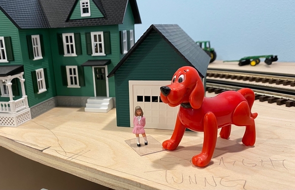
Dogs WILL be represented.  The one laying at my feet right now, as well as several in the scenery.  One of the things I love about layout tours is finding the little hidden details that make each layout fun and unique.  We will have a few, including Emily Elizabeth with her dog Clifford.  (As my adult children roll their eyes.  Gotta remember this was started when they were toddlers.)

IMG_7028

Attachments

Images (1)
  • IMG_7028
Last edited by Sather

This post is the current status of the build.  And back we go to painfully slow daily progress... not having a real plan or parts list results in a lot of time spent daydreaming possibilities.  "Thinking time" is what I like to call it, but in reality is just watching glue dry.  

Two of the corner plywood sections of upper are permanently installed, connecting land bridges just set in place to get a better idea of how things will fit before committing.  Sectional track has a lot of possibilities but some restrictions.  Actual bridges sitting on blocks to adjust the height to match the track after roadbed is added.  Structures also in temporary locations, looking for places to fit them to maximize long views.  i.e. may end up with building in front of wall light switch to block it from certain angles.  Duck-under in front of door will eventually become a swing-away.  

IMG_7009IMG_7012

Attachments

Images (2)
  • IMG_7012
  • IMG_7009
Last edited by Sather

Your layout is looking good.  Your story is similar to mine.  I had layouts from early teen years until my late 30s when our daughters were toddlers.  Then we moved, and I was going to build an HO layout, but it didn't happen.  Now they are aged 29 and 31, and I am into the 3rd year building a layout.  I retired a couple years ago, but had purchased most of what I need for a layout before that.  Yes a fall could be devastating.  I already have a replaced knee and lumbar fusion; I don't need any more hospital stays and recuperation.    I can't even imagine walking on my layout because I would have to hunch over too much.
@Sather posted:

Good point.  The walking around option is nice during the construction phase, but will actually go away once the tables get cluttered with stuff.  I figure I will finish the upper/outer before that happens to the lower.  The upper has no turnouts specifically to improve reliability, but you are right - problems occur in hard-to-reach locations, and falling at my age would be a life-changing experience.   May have to invest in one of those cantilevered ladders.  

I have a topside creeper.  Great for occasional use, but not something you want to spend a lot of time on.  Also, the legs require a lot of room to maneuver, and it has a big footprint for storage. 

@Sather posted:

Must. Love. Dogs.

Dogs WILL be represented.  The one laying at my feet right now, as well as several in the scenery.  One of the things I love about layout tours is finding the little hidden details that make each layout fun and unique.  We will have a few, including Emily Elizabeth with her dog Clifford.  (As my adult children roll their eyes.  Gotta remember this was started when they were toddlers.)

IMG_7028

I am glad to see the "dog" is full scale ! !

@PRR1950 posted:

Building the "swing-away" is best done early in the benchwork phase.  Adding the track support materials and electrical connections can be done later when you have a better idea of how the track will fit in that area.

Chuck

Thanks, Chuck.  Good advice.  The swing-away is pretty high on my to-do list.  I currently just have some of the upper benchwork propped up only to make sure the upper track will meet up after its trip around the perimeter of the room.  Since my track planning software was just copy and paste track sections drawn in MacPaint, it didn't have a very high level of precision, and I may need to adjust the benchwork / swing-out locations accordingly.  I was extremely lucky the lower lined up, with all the various curves and turnouts, using off-the-shelf sectional track.  If I had planned ahead, I should have trial fit the upper track on the lower table before starting the second level.  

Last edited by Sather
@ThatGuy posted:

I am glad to see the "dog" is full scale ! !

My daughter informs me that my reference in that post dates me and I need to explain it.  In my world, Emily Elizabeth is a character in a beloved children's book, the owner of Clifford the Big Red Dog.  In the rest of the world, Emily Elizabeth is an Instagram Influencer with 1.9 million followers and an OnlyFans account.

905x510_Clifford_Mezzanine_V2

Attachments

Images (1)
  • 905x510_Clifford_Mezzanine_V2
Last edited by Sather
@Sather posted:

...  Late start probably kept me from some expensive mistakes, ...  Rather than stuffing as much track into every square inch, I think we would be happier with a reasonable and realistic mix of track, structures, and scenery. ...


You're right. An expensive mistake that many novices commit ... like me.

Really nice track plan, and benchwork! Looking forward to seeing your progress.

@Mooner posted:

...   Going to have to make do with what we have and temper the benchwork based on current cost, but fortunately we have the trains and most of the track. Excited to start something later this summer and very happy for you that you are finally fulfilling a dream. Great patience and very nice work to date. Thank you for sharing.

Had a bit of sticker shock this morning.  Did I mention I work really slooooooow.   All of the benchwork to date is from pre-existing stockpile and leftover scraps from other projects.  Emptying out the pile of lumber in my garage while making the layout has been a symbiotic arrangement, making some room while losing some room.  Now that the lower benchwork is done, and about 2/3 of the way around the room with the upper, I finally needed to get one single piece of plywood.  IIRC, I paid something around $30 per sheet for generic 1/2" birch plywood.  Obviously quite a while ago.  Wow, same sheet today was over $90!  

Last edited by Sather
@Sather posted:

Had a bit of sticker shock this morning.  Did I mention I work really slooooooow.   All of the benchwork to date is from pre-existing stockpile and leftover scraps from other projects.  Emptying out the pile of lumber in my garage while making the layout has been a symbiotic arrangement, making some room while losing some room.  Now that the lower benchwork is done, and about 2/3 of the way around the room with the upper, I finally needed to get one single piece of plywood.  IIRC, I paid something around $30 per sheet for generic 1/2" birch plywood.  Obviously quite a while ago.  Wow, same sheet today was over $90!  

That is one that I can't click on 'like'!!

@Mark Boyce posted:

That is one that I can't click on 'like'!!

Thanks, Mark, for the empathy.  We are all in the same boat, living with inflation and shortages and all.  Suspect it will get worse before better.

Back to work on the layout.  Small project box added to table facade.  Plan a few more spaced around the layout to operate corresponding remote switches.  Not going to have a master panel as I like to follow the trains, which DCS makes possible.  

Also just finished a shelf for the transformers.  I originally planned a pull-out drawer, but the shelf works a little better in my application... it doesn't take any valuable space from the aisle.  I set the height to comfortably reach the throttle handles from a standing position.  Track Interface Unit will eventually mount vertically, making room for a second.

As I unboxed the Z4000's for the first time, I realize the throttles differ.  Both throttles on the left transformer are sloppy loose, while both throttles on the right one are both nice and firm.  Is there a good way to change the friction settings?

image001IMG_7058

Attachments

Images (2)
  • image001
  • IMG_7058
Last edited by Sather
@Sather posted:

As I unboxed the Z4000's for the first time, I realize the throttles differ.  Both throttles on the left transformer are sloppy loose, while both throttles on the right one are both nice and firm.  Is there a good way to change the friction settings?

Found it!  

https://ogrforum.ogaugerr.com/...e-tension-adjustment

Unfortunately, I was an "early adopter", so the loose one is a first generation version*  without the ability to adjust them.  Bummer.

* Going by the serial number, the first two digits being the month and the third and fourth digits the year.  The right (good) Z4000 is 0101#####, and has a little set screw on the case at the bottom of each throttle.  The left (loose) one is 0398#####, with no external screw.  The throttles do stay in position when moved, so still perfectly usable.  Hooked to a TIU they won't get moved much anyway.

Last edited by Sather

Made cardboard templates for, and then some of the cuts, in my recently purchased plywood.  If I plan and cut carefully, I believe this will be enough to finish the upper benchwork around the perimeter of the room.  There are two bridges (a 40" Atlas and a 50" MTH, both double track), which save the equivalent lengths in plywood.   With the price of lumber recently, the bridges are a bargain.  

On the east side of the layout, I was able to keep the lower track close enough to the front edge of the tables to reach everything, as well as to avoid creating more tunnels.  Already have three out of necessity, didn't want to overdo it.  

Rolo providing good company during the build.

IMG_7076IMG_7077RWZN7045

Attachments

Images (3)
  • IMG_7076
  • IMG_7077
  • RWZN7045

Weekend Update

South table, east end... O-72 is the minimum radius of the upper track, a requirement for some of the cars I want to run up there.  Several other corners have up to O-99 where possible, making nice sweeping curves.  This corner has the minimum O-72 on the inside of the curve, with O-81 on the outside, which keeps it nice and tucked into the corner where it would otherwise conflict with the exposed track on the lower table.  Don't know yet whether I will have a retaining wall or a steep rock face in the space between them.  

It doesn't leave much room on the outside of the curve, maybe some trees and a hill, but the Menards power company building seems to fit there nicely, and makes a logical end point for the high tension towers from MTH.  Again, thing just placed temporarily to get an idea where they fit while I get a feel for what is possible without overcrowding the layout.

IMG_0620

South table, west end - Front edges of the plywood just hanging free over the supports until I place the top track and know precisely where to cut it.  Easier to cut off a little extra than try and patch it back in if too short.  Parallel tracks of lower disappear in tunnel just this side of the MTH rust-colored bridge, will pop out again prior to siding visible on left side of picture.  That siding will be fully exposed and as long as I can make it, eventually having to end as the upper plywood edge comes from the left prior to where the tunnel portal is.

IMG_0619

Attachments

Images (2)
  • IMG_0620
  • IMG_0619
Last edited by Sather
@Sather posted:

Weekend Update

South table, west end - Front edges of the plywood just hanging free over the supports until I place the top track and know precisely where to cut it.

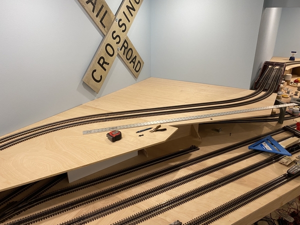
So, something like this.  The cut will be somewhere along where the ruler is.  The large flat area in the corner will leave me some room for structures not necessarily related with train operations, like downtown and residential, since there will be no switching or associated industry on the upper track.  And it is not easy to reach.  Although the long straight stretch (40") down the front would be an ideal spot for a passenger terminal.  

"Indecision is the key to flexibility."

IMG_7083

Attachments

Images (1)
  • IMG_7083
Last edited by Sather
@Sather posted:

So, something like this.  The cut will be somewhere along where the ruler is.  The large flat area in the corner will leave me some room for structures not necessarily related with train operations, like downtown and residential, since there will be no switching or associated industry on the upper track.  And it is not easy to reach.  Although the long straight stretch down the front would be an ideal spot for a passenger terminal.  

"Indecision is the key to flexibility."

IMG_7083

You could model the edge of a edge of a pine forest , with scale size trees 10 to 20"s ( rarely done on O gauge layouts) 

Last edited by Dave Koehler

Add Reply

Post
The Track Planning and Layout Design Forum is sponsored by

AN OGR FORUM CHARTER SPONSOR

OGR Publishing, Inc., 1310 Eastside Centre Ct, Suite 6, Mountain Home, AR 72653
800-980-OGRR (6477)
www.ogaugerr.com

×
×
×
×
Link copied to your clipboard.
×
×