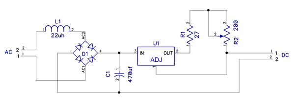
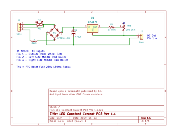
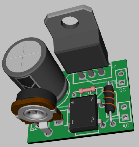
I can find 12v warm white LED strips on Ebay, but I am running conventional, so need 3 - 6 volt LED strips which will light using my 1033 PW transformer when I crack it on. Aren't the 12v strips for DCS or TMCC where there is contant voltage on the track? Or perhaps I need to use single LED's that light up at a low voltage ?? I already know how to build the circuit using a bridge rectifier, capacitor, and resistor. Any advice appreciated.
(19150dava)


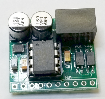

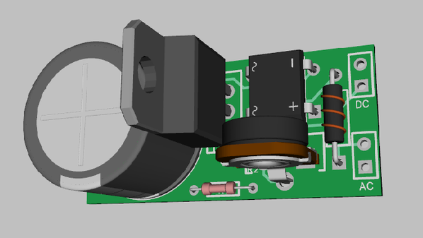


 3D")
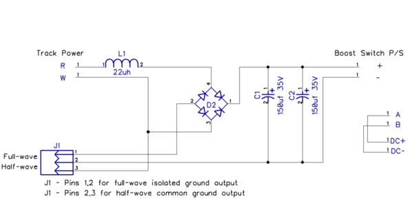
 Schematic")
 3D")
 Schematic")