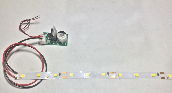
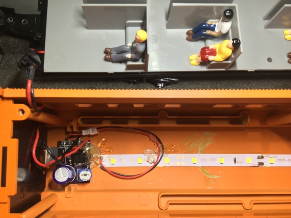
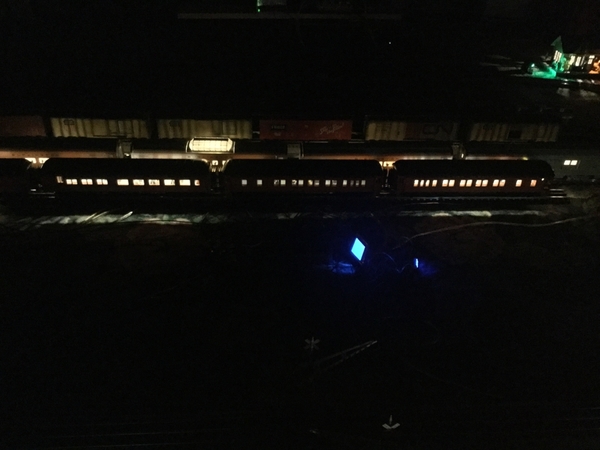
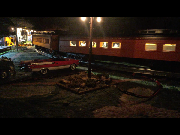
WB47:  I may be corrected here, but I don’t think cutting(shortening) a segment of the strip would have any effect on the brightness of each led.  Of course overall brightness would be impacted just because you’re using less lights in the car.  I have used only a single 3 led segment inside a Lemax building with the module, with no problems at all.

Actually Ted, prepare to be corrected!

The lighting module is a constant current design, so the pot sets a current value for the LED strip.  The current gets divided evenly with all the LED's on the strip.  If you cut some segments off, the remaining LED's get more current, thus they are brighter.  You can demo this yourself, just connect a strip segment to the lighting module, then parallel another strip segment.  You will see a visible reduction in the brightness of the LED's that were already lit.

I'd think you can count on one hand the number of guys using GRJ's off-the-shelf lighting modules willing/able to replace the microscopic surface-mount trimpot and/or resistor.

That said, has someone proposed tacking on a 2-cent resistor around ~2000 Ohms to any pair of copper islands at the boundaries of each section of 3-LEDs?  This would "steal" current from the output of the lighting module.  So while the module itself would retain its output range of 5-to-45 mA of current...the amount of current going to the LEDs would be downward shifted to, say, 0-to-40 mA since the resistor would steal ~5 mA of the output.  There is some math to work out.  

stan2004 posted:

That said, has someone proposed tacking on a 2-cent resistor around ~2000 Ohms to any pair of copper islands at the boundaries of each section of 3-LEDs?   

Stan, you only need one resistor, right across the feed to the LED strip, I've tried this.  Values from 2.2K and down will vary the brightness of the LED's significantly without modifying the board.

cjack posted:

With silhouette windows you can put it on the floor...works well I found. But with the interiors you really have to put it on the underside of the roof. I haven't done a dome car.

Here's another thread where I did a dome and the observation cars.  Sometimes I can run the dome lights overhead if there's a roof panel, but for this upgrade, I had to do a sidewall mounted LED installation, no place on the roof!

Passenger car LED lighting (Again)

gunrunnerjohn posted:
stan2004 posted:

That said, has someone proposed tacking on a 2-cent resistor around ~2000 Ohms to any pair of copper islands at the boundaries of each section of 3-LEDs?   

Stan, you only need one resistor, right across the feed to the LED strip, I've tried this.  Values from 2.2K and down will vary the brightness of the LED's significantly without modifying the board.

John and Stan,

Your recent posts were interesting so I decided to do some experiments.  I found that a 3k resistor will just slightly dim the LEDS.  I also found that really low values, 270 Ohms for example, turns the LEDS off completely and immediately.  Anyone wanting to do this should start with John's 2.2K value and work their way down to get the desired brightness.

I also verified that the LEDS brightness does vary depending upon the number of LEDS attached.  More LEDS, less brightness.  That wasn't as noticeable when you just hook up different numbers of LEDS depending upon car requirements.  In some cars I used 15 LEDS and in a couple of baggage cars only six LEDS.

gunrunnerjohn posted:

The reasoning why low values kill the LED's is simple Greg.  Since the circuit supplies constant current, a very low value resistor shunt will simply use all the current available long before the voltage across the load gets high enough to light the LED's.

I actually thought any resistor connected across the supply would cause a short and kill the LEDS.  I was surprised when the higher value resistors didn't cause a short.  See I learn new things all the time around here.

TedW posted:

Where exactly would you place those ~ 2k +/- resistors to retrofit an led converted car?

E770B966-87AD-497B-9915-395F206EEDE0

Ted,

Here is a picture of where to connect the resistor to the LED strip.  I show a through hole resistor but a surface mount might be a better option if soldering to the LED strip.

image

Question for @gunrunnerjohn or @stan2004 does it matter if the board is constant current or constant voltage?

Attachments

Images (1)
  • image
GregM posted:

Here is a picture of where to connect the resistor to the LED strip.  I show a through hole resistor but a surface mount might be a better option if soldering to the LED strip.

image

Question for @gunrunnerjohn or @stan2004 does it matter if the board is constant current or constant voltage?

The behavior will be different.  If you have a constant voltage supply, the resistor would have to be in series with the power source. 

The reason the resistor is across the power source in this example is the supply is supplying a fixed amount of current, so by siphoning off current with the resistor, you have less current for the LED's, hence they are dimmer.

With a constant voltage supply, adding resistance across the power just increases the power consumed, but it doesn't change the voltage until you exceed the current capacity of the power supply, so the LED's are the same intensity.  Putting the resistor in series drops some of the voltage and dims the LED's.  The value of the series resistor will be dependent on the number of LED's you're powering, since the more current the LED's draw, the more voltage drop you'll have across a given series resistance.

Last edited by gunrunnerjohn
GregM posted:

Here is a picture of where to connect the resistor to the LED strip.  I show a through hole resistor but a surface mount might be a better option if soldering to the LED strip.

...

Question for @gunrunnerjohn or @stan2004 does it matter if the board is constant current or constant voltage?

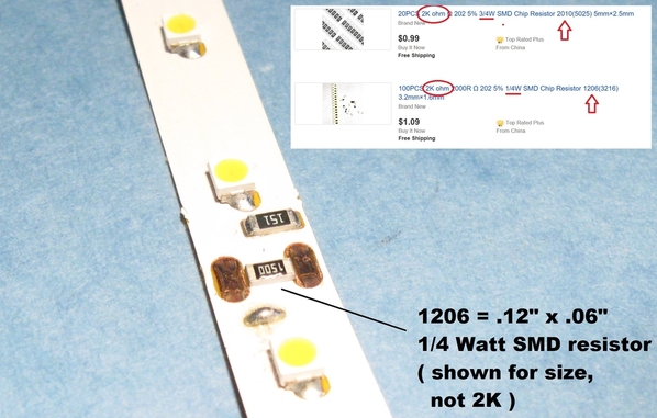
1206 shunt on led strip

Right.  An SMD resistor might be easier to install and more tidy...of course you must have suitable eyesight to deal with tiny components!

So a couple comments about using an SMD resistor.  You want a power handling capability of 1/4 Watt or more (this also applies if using a leaded resistor as in GregM's photo).  In above photo, I show a "1206" size (.12" x .06") SMD resistor which is 1/4 Watt.  The value is not a 2K but this is for sizing only.  They are only a penny each on eBay but may be difficult to install since they just barely "straddle" the copper islands on the LED strips.  I'm sure you could do it but may get frustrating applying huge blobs of solder.  Your mileage may vary.

That said, you can also get slightly larger SMD resistors.  For example a "2010" size (.20" x .10") would nicely straddle a pair of copper pads and be easier to solder to the pads..as well as being physically larger and hence easier to see and manage!  A tad more expensive at 5 cents each so you may need to save up your allowance.

---

This resistor shunt method for dimming only works for constant-current boards like GRJ's lighting module.

Attachments

Images (1)
  • 1206 shunt on led strip
Last edited by stan2004

For those of you guys that want to earn DIY'er extra-credit, I found this video from an earlier OGR thread demonstrating how to apply the shunt resistor to dim an LED strip driven by GRJ's lighting module.

Idea 1.  Dim/bright lighting for night/day running.

So rather than a set-it-and-forget-it brightness.  If you install a simple 25 cent on/off switch with the new resistor, you can simply flip the switch to enable/disable the resistor.  You might have to cut a hole in the bottom of the car chassis to install the slide switch but you could at least then quickly convert the brightness between bright and dim.

Idea 2. Dim/bright (or off/on) lighting for passenger station loading/unloading.

Or using a 50 cent latching magnetic Hall sensor chip, a 10 cent magnet can enable/disable the external resistor to change the brightness of the LED strip.  As the video shows, as the train arrives at the station, the lights turn up so that passengers can get their luggage and load and unload at the platform.  When the train leaves the station, the lights dim so the passengers can get some shut-eye.

Last edited by stan2004
gunrunnerjohn posted:

Stan, where did you find the latching magnetic sensor, that's pretty cool!

In my parts bin.  LOL. 

Or, for Digikey disciples: https://www.digikey.com/produc...k=1&pageSize=500

What I think is cool about these devices is you can simply attach the "circuit" using 2-wires to any pair of copper pads on the LED strip.  Place the sensor on a wall of the passenger car.  Then use the "north" pole of a magnet to set the brightness to one level, use the "south" pole of a magnet to set the brightness to another level.  Lather, rinse, repeat.

Last edited by stan2004
stan2004 posted:
gunrunnerjohn posted:

Stan, where did you find the latching magnetic sensor, that's pretty cool!

In my parts bin.  LOL. 

Or, for Digikey disciples: https://www.digikey.com/produc...k=1&pageSize=500

What I think is cool about these devices is you can simply attach the "circuit" using 2-wires to any pair of copper pads on the LED strip.  Place the sensor on a wall of the passenger car.  Then use the "north" pole of a magnet to set the brightness to one level, use the "south" pole of a magnet to set the brightness to another level.  Lather, rinse, repeat.

Hey Stan.....you absolutely CRACK ME UP! I've been educating myself (reading all your fantastic post RE. Track Occupancy) to use them to trigger Atlas Signal System. Your posts are absolutely outstanding! 

Last edited by Junior

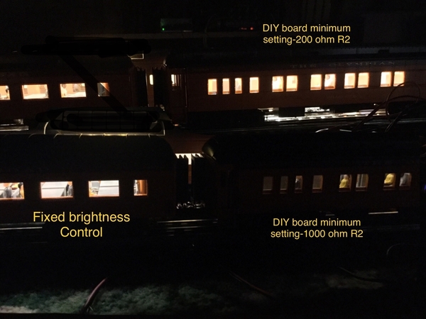
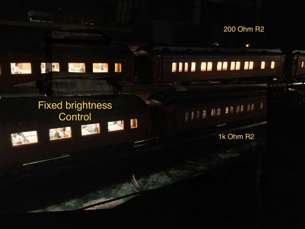
TEDW, that 1k R1 certainly does dim the leds way down. If you like running in simulated "night" conditions, that looks like the way to go. Most of my running is done at "dusk" or brighter conditions, so I like them a little brighter. Just personal taste.

Maybe what we need is a photocell that detects the room light level, and adjusts the leds accordingly? Grj, stan, what do you think, possible?

Rod

Rod Stewart posted:

TEDW, that 1k R1 certainly does dim the leds way down. If you like running in simulated "night" conditions, that looks like the way to go. Most of my running is done at "dusk" or brighter conditions, so I like them a little brighter. Just personal taste.

Maybe what we need is a photocell that detects the room light level, and adjusts the leds accordingly? Grj, stan, what do you think, possible?

Rod

Rod, the 1k pot is at R2.  I’m sure you have a typo there.  You are right, night time running is subdued lighting.  I don’t think I will use the minimum brightness setting with the 1k pot.  I will try the 500 ohm too when they get here tho.

Rod Stewart posted:

...

Maybe what we need is a photocell that detects the room light level, and adjusts the leds accordingly? Grj, stan, what do you think, possible?

Certainly possible.  That is, a circuit that uses a photocell to shunt a variable amount of current (depending on room light level) from the LED strip would only cost, say, $1 in parts.  OTOH if fiddling with brightness control, I'd think most guys would want direct access to set lights bright vs. dim, or on vs. off.  In my opinion of course!


TEDW, yes I meant R2 = 1K of course, my mistake, duh. Anyway glad that is working for you.

I have my first few cars done using grj's roll your own modules with R1 of 12 ohms and R2 of 100 ohms. This gives an output range of about 12 to 100 ma. The cars are 15" so I am using 14" long led strips, with 21 leds per car. For a first run I have them set at 90 ma output, so just over 4 ma each, and they are quite bright. For now I like how they look, I may run them a while like that then crank them down a little. Time will tell.

In thinking about the photocell variable brightness idea, I guess it would be overkill and unnecessarily complex. Plus everytime the train went under a bridge or through a tunnel the lights would dim, which would look kind of odd. 

Rod


Last edited by Rod Stewart
Rod Stewart posted:

...

I have my first few cars done using grj's roll your own modules with R1 of 12 ohms and R2 of 50 ohms. This gives an output range of about 12 to 100 ma. The cars are 15" so I am using 14" long led strips, with 21 leds per car. For a first run I have them set at 90 ma output, so just over 4 ma each, and they are quite bright.

If you're using the standard 12V LED strips, note that they are 2" (5 cm) sections of 3 LEDs...with each LED within a section receiving the same current.  So your 14" strip is being split into 7 x 2" sections with each section driven by about 13 mA (90 mA / 7).  Hence each LED is also 13 mA.  And, as you and others have reported, 13 mA LED current is mighty bright for O-gauge passenger car LED strips.

Rod Stewart posted:

...

In thinking about the photocell variable brightness idea, I guess it would be overkill and unnecessarily complex. Plus everytime the train went under a bridge or through a tunnel the lights would dim, which would look kind of odd.  

I don't think $1 for a few generic parts (photocell, 2 resistors, 1 transistor) is complex...especially if it attaches to the LED strip with just 2 wires.  Ironically, by using a 5 cent capacitor like on GRJ's lighting module, you can implement flicker rejection on the photocell circuit.  In other words, it would average the ambient lighting over many seconds or even minutes.  So short term variations don't change the LED brightness. 

Junior posted:
 

Hey Stan.....you absolutely CRACK ME UP! I've been educating myself (reading all your fantastic post RE. Track Occupancy) to use them to trigger Atlas Signal System. Your posts are absolutely outstanding! 

Well, as long as you're laughing WITH me and not AT me!


I typically run the LED's in 18" cars with 25-30ma from my constant current regulator, that's 24 LED's in 8 groups of three.  It gives nice illumination, even with fairly bright room lighting that's about 3-4ma through the LED's.  I can't imagine what they'd look like if I ran the LED's with 13ma, but they'd be WAY brighter than I like them!

Here's my Superliner upgrade, this has 39 LED's in 13 groups of three.  I cranked this one up to a measured 35ma from the regulator, so that's around 3ma for each LED.  I am considering popping the top and cranking them down a bit.

Attachments

Images (1)
  • mceclip0
gunrunnerjohn posted:

Actually, those are warm white, they just look whiter in the photo.  FWIW, that's in a brightly lit room as well.

We may have different definitions of "decent brightness level".

John, I wouldn't change a thing. Those look great to my eye, realizing of course that pictures can be deceiving.

Aside, I had one dud of the 12 boards I prebuilt while in AZ. Turned out to be a bad solder joint on the 317. Replaced it and all is well. One thing I don't like about OSH Park boards is that the pads are not tinned. This makes them challenging to solder, but doable. The bulk lot of boards I ordered from Allpcb has arrived and I am happy to see the pads are tinned. They should be easier to deal with. These boards look really good BTW. 

Rod

John, check on back in the north country. Not too bad up here, full on spring. Snow was thankfully long gone by the time we arrived.

I am using good old 63/37 rosin core solder, which has always worked very well for me. Not sure what would be any better? And I have only been soldering stuff for close on to 60 years or so. 

Maybe a quick dab with TixFlux just before soldering might help, I may give that a try.

Rod

Rod, those cars look great.  

I have eight PCB's (third layout design) populated with components, tested, ready to go but who knows when I will get around to installing them.  I still have the PE disappearing hobo car to convert, concerned about light leakage around the movable hobo.  Was planning to convert my Lionel Lines Irvington cars next, but after seeing your cars above, maybe I need to do a non-silhouette set of cars instead.

GregM, I hear you, and thanks for the comments. I think cars with so called "detailed interiors" make the most sense, I don't think I'll bother with silhouette cars, but there's certainly nothing wrong with that. Time will tell. After the first car I think I'm down to under an hour per car, at least for standard cars. Definitely a dome car takes longer, as does an observation. The worst one was the vista dome car because I had to cut out the entire center section of the clear plastic dome window insert, to make space for the led strip to mount up against the underside of the top. I did this quickly with a dremel cutoff wheel, then it took forever to file all the rough edges down. But in the end it worked well.

A few more pix:

IMG_1868IMG_1869IMG_1876IMG_1877

Attachments

Images (4)
  • IMG_1868
  • IMG_1869
  • IMG_1876
  • IMG_1877

I did a set of IC silhouette cars and they looked great compared to the two bulbs that they came with. I have since only collected detailed interior cars and sold all the silhouette car sets. I have yet to do these cars which have incandescent stream lighting and really look pretty good without LEDs. But it would be nice to have constant power.

Rod Stewart posted:

After the first car I think I'm down to under an hour per car, at least for standard cars. Definitely a dome car takes longer, as does an observation. The worst one was the vista dome car because I had to cut out the entire center section of the clear plastic dome window insert, to make space for the led strip to mount up against the underside of the top. I did this quickly with a dremel cutoff wheel, then it took forever to file all the rough edges down. But in the end it worked well.

We're going to have to get you to step up your game.   I can whack out an MTH premier car in about 15 minutes, it takes me longer to seat all the passengers that it does to wire the LED lighting.  The MTH RailKing and Lionel cars actually take me longer, usually you have to deal with some extra wiring issues.  Here's a set I did recently for the RK MTH Crusader.

Passenger car LED lighting (Again)

You'll see the dome car and observation cars take some special handling as you indicated.  I didn't hack the top, I went with seat level lighting in the dome car.

All my small wiring is #30 wirewrap wire, works great and is easy to hide and route where you need it.

John, I am hoping I will be able to speed it up a bit after I get a few more under my belt (passenger cars that is! )

First impressions running though; great! No flickering and plenty of light. My passengers can now see what they are doing. They might be a little too bright, so I may crank them down a bit someday. And I need to add the marker light leds to the observation car, thanks for those ideas in the thread you pointed to John. I am also pleased to report that with the offshore parts I ordered after the first batch, and my bulk board order from AllPCB, my cost per board is now down to $1.03 all in. Well not including my time of course.

My wiring from the module to the led strips is very light, about 30 AWG I believe. I ordered a bunch of micro JST 2 pin male/female connectors referenced earlier in this topic; about 10 cents a pair. They are perfect. So far I have been able to adapt the wiring already in the car to supply power from the rollers to the board input, after clipping off the unneeded light wires. So that's kind of handy. Works just fine. All in all it has been a good experiment so far.

Rod

Here is a front/back pic of the bulk boards: The pads are pre-tinned; yahoo!

IMG_1885

Attachments

Images (1)
  • IMG_1885
Last edited by Rod Stewart

That this thread is revived today is a little spooky.  This morning I dug out the PRR Baby Madison passenger cars I had started adding passengers to and converting to LED lighting last year. The observation car was the only car I had finished by the time the weather had become warm enough to start fishing, so the rest were packed away for another day.  Well another day finally came, lol.

Turns out I didn't have any pictures of the PCB with the PTC on the board.  I am working (very slowly, I will admit) on upgrading some cars so I just took the pictures below, they are straight from the camera, no editing.

Bare board - Component side.

PCB Ver 1.1 - Pic 1


Bare Board - Solder Side  (CR1 & CR2 are the center roller connections)

PCB Ver 1.1 - Pic 2

Components installed - view one

PCB Ver 1.1 - Pic 3

Components installed - View two

PCB Ver 1.1 - Pic 4


Board being installed

PCB Ver 1.1 - Pic 5


Double sided tape - board hopefully will stick to roof out of sight

PCB Ver 1.1 - Pic 6

Attachments

Images (6)
  • PCB Ver 1.1 - Pic 1
  • PCB Ver 1.1 - Pic 2
  • PCB Ver 1.1 - Pic 3
  • PCB Ver 1.1 - Pic 4
  • PCB Ver 1.1 - Pic 5
  • PCB Ver 1.1 - Pic 6
Last edited by GregM

Here is a link to the board on OSH Park.

https://oshpark.com/shared_projects/Ah9bQ5RM


This is just a quick BOM. 
This first section contains the actual parts I ordered from Digi-Key.
Digi-Key Part Number
Manufacturer Part Number
Manufacturer
Description
DF005M-ND
DF005M
ON Semiconductor
BRIDGE RECT 1PHASE 50V 1.5A 4DIP
 
‎LM317TGOS-ND‎
‎LM317TG‎
ON Semiconductor
IC REG LIN POS ADJ 1.5A TO220AB
 
P5168-ND‎
‎ECA-1VM471‎
Panasonic Electronic Components
CAP ALUM 470UF 20% 35V RADIAL
 
490-4808-1-ND‎
‎PTGL07BB220N0B52A0‎
Murata Electronics
PTC RESET FUSE 250V 130MA RADIAL
 
277-1722-ND‎
‎1984620‎
Phoenix Contact
TERM BLK 3POS SIDE ENT 3.5MM PCB
 
277-1721-ND‎
‎1984617‎
Phoenix Contact
TERM BLK 2POS SIDE ENT 3.5MM PCB
 
 
This section contains Digi-Key parts comparable to items I purchased from other sources, primarily Amazon.
Digi-Key Part Number
S27QCT-ND 
Manufacturer
Stackpole Electronics Inc
Manufacturer Part Number
CFM14JT27R0
Description
RES 27 OHM 1/4W 5% CF MINI

Digi-Key Part Number
3296W-201LF-ND 
Manufacturer
Bourns Inc.
Manufacturer Part Number
3296W-1-201LF
Description
TRIMMER 200 OHM 0.5W PC PIN TOP
 
Although there is a place for it on the PCB, I did not install the DCS choke (L1 on the PCB).  I believe an appropriate part number is listed somewhere in this multipage thread.
 
***ETA***  If I researched this correctly, here is an appropriate part for the DCS choke.
 
Digi-Key Part Number
535-14428-1-ND 
Manufacturer
Abracon LLC
Manufacturer Part Number
AICC-02-220K-T (5K/REEL)
Description
FIXED IND 22UH 285MA 1.35 OHM TH
 
Hope this helps.
Last edited by GregM

I'm wondering what LED strips people are using and what color / temperature LEDs.  Where is a good place to buy LED strips.  I also may want to use board connectors in some projects.  Does anybody have the part numbers for the 2 pin board connector and the male end for it.  I have looked but there are so many out there, I don't want to guess at which ones work.

Thanks in advance.

What myself and others tend to use for passenger car lighting is strip leds size 3528 with 3 leds per 2" length. Warm white seems to produce the most realistic lighting. They are commonly available in 5m or 10m reels in 12vdc voltage range. AliExpress or ebay are good sources. Domestically Amazon has them also.

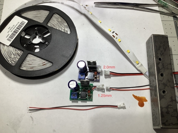
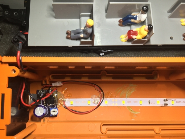
For connectors I have found JST-PH 1.25 work quite well. They are available on ebay in lots of 20 each male and female, for under $2. I buy about 4 or 5 lots at a time, usually with all shipped for the same cost as 1 lot would be. The header pin pitch is 0.1" on the board so you can also use any header you like including JST XH or JST EH, or Dupont pin headers, as well as others. What I do is solder the wires of the small 1.25 headers above directly to the board, then the mating end gets soldered to end of the led strip. This way the strip can be easily disconnected for car maintenance anytime. For the ac power supply side I just cut off the wires that supply the original lighting and solder them directly to the board.

16" cars can usually accomodate a strip 14" long, so 7 sections, 21 leds total. 18" cars use a 16" strip 24 leds, and 21" cars use an 18" strip 27 leds.

hope that helps,

Rod

Figured I would ask in an older created topic about passenger cars.

Please correct me if I should not be doing this as I have several times because I would hate to create a new topic for a simple question, but I do not want to hijack a current topic thats fairly active at the moment (which this does not seem to be). My question is...

I am looking to purchase a o31 capable passenger car set with led lights.

How many years can I go back to know it would have LED lighted interiors? I have my eyes on an MTH Railking set from 2013 but cannot find if they are LED lights.

Brad

2013 will almost certainly still be incandescent bulbs.  Truthfully, starting a new topic for something like this would probably be a good idea, and you might also give us the actual product number of any candidates.  Truthfully, I don't see any of the Railking line with LED lighting mentioned, so they may not have gotten there at all.  The Premier cars started getting LED's around 2017 I believe, and they're mentioned in the product listings.

What he said. 

Out of curiosity what is it about LED lighting makes this a deciding feature?  I only speak for myself of course but it seems you'd choose passenger cars because it's the right model/style/era, or right road name, etc. rather than if it had LED vs. incandescent bulbs.

I assume you are specifically referring to the interior lights.  There have been cars using bulbs for interior lighting but LEDs for, say, the marker lights.  Also, if you're operating conventional mode the issue of what is often called constant-voltage lighting (same brightness irrespective of track voltage) is not a given just because it's LED technology.  Likewise, flicker tolerance is not necessarily a given just because it uses LED technology.   

Just want to be sure you're getting what you want!

It's all what your taste are when it comes to LED color.  I went with warm light for my conversion.   EBAY is a four letter word on OGR.  Not sure links are allowed.  Search for LED light strips brings up hundreds.  I also purchase LM117 buck converters on the bay also.  Just add a full wave bridge rectifier on the input, maybe a filtering cap and set the output voltage to the desired brightness.  Did 11 MTH madison cars for less than 40 bucks.

Last edited by superwarp1

The color temperature of the LED's will depend on the era of the passenger cars.  For instance, the old Woodside passenger cars look best with yellow or amber, also heavyweights I like to go that way with as well.  Slightly more modern cars I go with the warm white, 2700-3000K wavelength.  For truly modern cars that you want to emulate florescent lighting, consider the bright white strips.

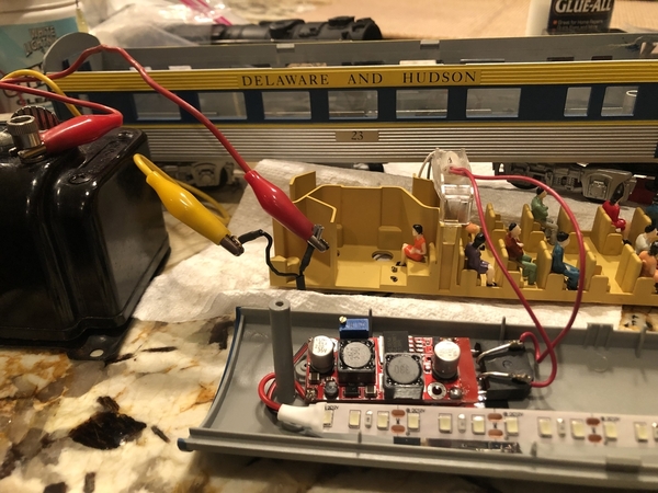
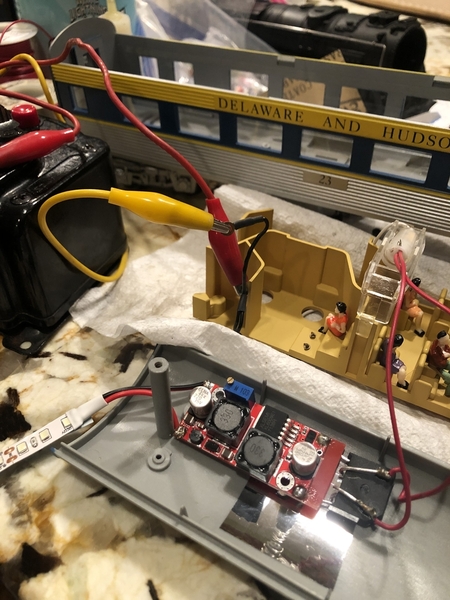
Consider this eBay module, auction #: 122186424028, $1.39.  Add a bridge rectifier in front of the input to convert the AC to DC, and you have constant intensity adjustable lighting with any input voltage.

Boost Buck DC adjustable step up down Converter XL6009 Module Voltage


Hi John,

Need your help!!!   Please check the photo I've attached. I have an MTH passenger car that I put this boost buck board in (per your good advice) and tested it with my trusty 1035 transformer. I measured 12.5vac from the transformer before I connected the alligator clips to the power leads. (the black leads connect to the truck) the power from the truck goes to the bulb which I routed to my bridge rectifier.... then the output of course, goes to about a food of LED lighting strip. All was good until....the circuit and LED's began to get red hot. I shut the transformer immediately.  Do I need a properly placed dropping resistor??? As usual, your help is greatly appreciated.... IMG_3152IMG_3150IMG_3151

Attachments

Images (3)
  • IMG_3152
  • IMG_3150
  • IMG_3151

I see the proper advice is already arrives in duplicate.   The voltage you want for proper lighting with the 12V strips will likely be in the 9-11 VDC range.  I'd start around 9V and then tweak the pot for the brightness desired.

When I was a kid I used to have the urge to competitively raise my hand first in class…not so true anymore, but still fun once in a while

I’m enjoying your layout updates John!

Funny thing Chuck, I was known as the Question Man in school.   I carried that on to my career.  It would really surprise someone when a question came up and instead of trying to BS them with an answer to make it look like I actually knew the topic, I'd say "I don't know, but I can find out".  More than once they wouldn't have any idea how to react to that.

Funny thing Chuck, I was known as the Question Man in school.   I carried that on to my career.  It would really surprise someone when a question came up and instead of trying to BS them with an answer to make it look like I actually knew the topic, I'd say "I don't know, but I can find out".  More than once they wouldn't have any idea how to react to that.

Great answer! I’m gonna copy that…

@TedW posted:

BCianci, there’s usually a lot of adjustment in that blue pot, so just keep turning  and it will start to go down.  I run some of my cars around 8vdc.  During night running, they look very nice, but when all the house lights are on don’t show up as much as 9-10vdc.  YMMV

Really good observation. I have been using those pot for 60 years (yikes) and always wonder where I am on the pot. Keep turning until nothing changes, then go the other way to get what you want.

Last edited by cjack
@TedW posted:

BCianci, there’s usually a lot of adjustment in that blue pot, so just keep turning  and it will start to go down.  I run some of my cars around 8vdc.  During night running, they look very nice, but when all the house lights are on don’t show up as much as 9-10vdc.  YMMV

I’ve got about 1 foot of LED strips in each passenger car how long are the LED strips you are using at 9 V?

I see the proper advice is already arrives in duplicate.   The voltage you want for proper lighting with the 12V strips will likely be in the 9-11 VDC range.  I'd start around 9V and then tweak the pot for the brightness desired.

Okay, so: my circuit board was adjusted to 22 volts... which apparently is enough to generate a lot of heat in both by CB and LED strip.  Anyhow, I took John's advice and lowered to about 9 volts...  I'm a very happy man... Thank you.

I'll bet the LED's were pretty excited to see 22 volts!   At 9V, the power supply is loafing, and the LED's are drawing a small fraction of what they were.  You probably were over-driving the LED's by a factor or at least 4x their maximum current!  The wouldn't have lasted long if you kept that up!

Would the circuit board be "happier" if adjusted the output up to 12v ? (yes, I'm seriously asking this stupid question).

Add Reply

Post

OGR Publishing, Inc., 1310 Eastside Centre Ct, Suite 6, Mountain Home, AR 72653
800-980-OGRR (6477)
www.ogaugerr.com

×
×
×
×
Link copied to your clipboard.
×
×