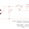
GRJ, thank you for the information you provided above.  It has been a long time since l did electronic "stuff."  A couple questions if you don't mind, what is the reason for "common ground" setting with LED lights?  Also would adding a resistor between the unregulated DC and the module be sufficient to prevent voltage overload?


The reason for my option was as I stated, sometimes I need a common AC and DC ground.  Other times, such as my passenger car lighting module, I don't have that requirement and I use a bridge rectifier.

The resistor is probably not going to do the trick.  You can buy the proper 28V rated module for the same price on eBay, that's the way I'd go. 

You could use some back to back 5V Zener diodes to drop the voltage a bit for each module.  A kludge, but it works.  You still need the other components, rectifier and capacitor, also the choke if you use DCS.

If you're going to get into soldering components together, you can probable roll your own easier than using the modules.  For low currents for LED lighting, constant current is the way to go.  You can tune the brightness by varying the resistor value.  This is basically how my lighting modules work.

Constant Current LED Passenger Car Lights

Attachments

Images (1)
  • Constant Current LED Passenger Car Lights
Last edited by gunrunnerjohn

I go with 35V capacitors, they've always been sufficient.  The voltages on 18 volts end up being in the 26 volt range on the capacitor.  25V capacitors would probably fail pretty quickly with that voltage.  The circuit above is good for around 50ma without any heatsink, if you're driving 12V lighting strips with an 18V AC power supply, that results in .8 watts power dissipation in the LM317.  It'll get around 70C or so, but within it's operating ratings.  If you want more current, add a heatsink to the TO220 regulator package.

If you haven't yet placed your DigiKey order consider a 40 cent trimpot to adjust brightness.

http://www.digikey.com/product...1/3306F-201-ND/84621

In place of a fixed-value R1 in GRJ's diagram above you could use, say, a 27 ohm resistor in series with a 200 ohm trimpot to give an adjustable R1 range of 27 to 227 Ohms.  This would give a current range of about 5 mA to 45 mA.  This adjustment method is discussed/documented in one of GRJ's previous posts.

I realize you're not doing eBay but for anyone contemplating a roll-your-own you can get 200 ohm trimpots on eBay for about 10 cents each shipped.

200 ohm trimpots for 10 cents each

Attachments

Images (1)
  • 200 ohm trimpots for 10 cents each
Last edited by stan2004

Hi all - I did this conversion to my Polar Express but something seems amiss (don't want to hijack the thread): I don't have constant brightness (it still varies with power applied), and now there are tiny sparks/crackling where the wheels meet the rails when it rolls.  There's a very small hum too, changing pitch depending on power applied and whether or not the light strip is attached to the Buck (no strip = no hum).

I used these components:  Buck Converter,  Light string (3528)Bridge Rectifier, 220uf capacitor.  Piece of cake to solder up.  I removed both bulb sockets in there and ran the incoming power wires to one "~" of the bridge and the incoming black wires to the other "~".   "+" and "-" out to the Buck.  The power wires have a stripe on them (at least one does) and initially attached to the red wires of both sockets, opposite for the black wires.

The light string for the car lights up so I know the AC-DC conversion is happening.  Could something be improperly grounded or crossed (I don't see how, but...)?  Are my components wrong?  What should I check?

Thanks much

It has only been two years, but I finally sat down this month and learned enough about the KiCad EDA program to design a PCB to use the parts bought back in 2017.  Only ordered three PCB's from OSH Park to make sure I didn't screw up somewhere along the way.  Now to just wait for them to get here.

I believe I have the PCB matching the schematic, PCB layout passed all of KiCad's checks.  I just don't know if I left enough room around the components (using through hole for now) to be able to actually populate the board.  I think so, but we will see in a couple weeks or so.  I reworked the PCB a couple of times to get its dimensions under 1 inch by 2 inches.


Greg did say he's using a through-hole component design...a wise first step.  The components in his version would be about 50 cents per board in small quantities on eBay.  So even if the extra square inch increases board cost, in DIY quantities it might be a wash if eBay from Asia is an option.  Then there's the assembly and handling hassles of surface-mount parts which require the dexterity and eyesight of a teenager.  


Edited to clarify board dimensions.

This is the very first PCB I have ever had produced for me.  I only ordered three boards this go around for prototyping.  I hope I get better as I go along but for this time I was content when I got the board under two inches long, first layout was about 2.25 inches long.  Decreasing the board length did bring the cost down from my first attempt.  I really don't intend to produce that many boards in the long run, but if eventually these boards help others that would be nice.


P.S.  I never had the eyesight of a teenager when I was a teenager, let alone now.


Last edited by GregM

Add Reply

Post

OGR Publishing, Inc., 1310 Eastside Centre Ct, Suite 6, Mountain Home, AR 72653
800-980-OGRR (6477)
www.ogaugerr.com

×
×
×
×
Link copied to your clipboard.
×
×