Pingman posted:GRJ, for complete novices like me, what is the optimum way to go about assembling these "kits"?
Well, other than do the short parts first, not much to it. Just don't put anything polarity sensitive in backwards. ![]()


|
|
Pingman posted:GRJ, for complete novices like me, what is the optimum way to go about assembling these "kits"?
Well, other than do the short parts first, not much to it. Just don't put anything polarity sensitive in backwards. ![]()
Along with Johns note on squeezing in the tiny resistors and diodes first, I'd include surface mount parts to that list of firsts too.
I like to work from the center to the edges. On large, tight boards, I may fit the large suff first, "just incase". If there is a problem fittlng something, it's usually because of part change, etc. (change in overall size, different case shape or even leg orientation, etc) it is most often easier to change position of a small part (like instead of flat, you can solder one end close to the board and stand it straight up, and use the long leg looped like a candy cane, for going back to the board.)
On small boards it hardly matters.
Bending legs slighty to the side/opposite ways/etc. to hold the piece (or 4), solder, clip excess leg off ..... "Next!" ![]() ...next,next next, clean solder flux of board, install and call it done.
...next,next next, clean solder flux of board, install and call it done.
TedW posted:Parts came in yesterday.
Am giddy with excitement.
Where are those boards? Dang! I just stepped on something slick.

Haha, don't worry, you will get over it! ![]()
Rod
Adriatic posted:I like to work from the center to the edges. On large, tight boards, I may fit the large suff first, "just incase". If there is a problem fittlng something, it's usually because of part change, etc. (change in overall size, different case shape or even leg orientation, etc) it is most often easier to change position of a small part (like instead of flat, you can solder one end close to the board and stand it straight up, and use the long leg looped like a candy cane, for going back to the board.)
One thing you clearly should do, especially with a new board design, build ONE and see if everything fits. Don't ask me how I know this. ![]()
How about: ".... build ONE and see if everything fits, AND see if it works!" ![]()
Rod
Well... yes, it would be nice if it worked. ![]()
gunrunnerjohn posted:Well... yes, it would be nice if it worked.
John, I have NO doubt! 👍
Rod
I don't want to flog a dead horse but just FWIW here is a snip of my revised BOM as ordered 01-27-19. All onshore parts have arrived; offshore are still somewhere out there. Waiting for the OSH Park boards to arrive so I can do a test fit. Looks like they are due to ship about Feb 5. ![]()

You can see my all in board costs are $2.45 for the 45 ma version and $2.77 for the 100 ma version, not including fab time of course. The latter is primarily due to the higher cost of the 1000 uf cap C1. Interestingly I calculate that at 100 ma the load on the 12 ohm R1 resistor will be right at its rated 1/8 watt, so it will likely run a little warm. Had I known this at the time of ordering I would have ordered 1/4 watt resistors instead. For any about to order the 12 ohm resistors, maybe consider 1/4 watt. For the 27 ohm resistors 1/8 watt is fine.
I ordered the pots and the LM317's offshore primarily due to better pricing, and it looked like the 317's were out of stock at Dig-Key at the time. Longer delivery times of course, but I can't build any of these until we get home in April anyhow, though I can test fit the components I have. The offshore pots look like knockoffs of the Bourn 3362P units, so dimensionally they should be good. (The vendors even call them "3362P") These are rated at 1/2 watt, so there should be no power or overheating issues.
Rod

I don't expect to get my first three boards from OSH Park until sometime after Feb 8th. The revised boards sometime after Feb 12th.
Rod, I’m having a brain freeze on your math in the 45mA section. Specifically, the board price total of $63.34. How do you get that number based on quantity 12 ordered? On my order of 18 boards was only $22.80 at $3.80 per batch of three. Would you explain?

TEDW; yes that does read kind of weird. The $63.34 is based on the build quantity of 50 in the upper yellow cell, and would be the total had I ordered the full 50 boards. I only ordered 12 boards to start with as shown to the right of that total, because I wanted a small quantity to test and make sure they meet expectations. I figured 12 would be good for starters as it will be enough for 2 sets of cars. If all is good I will then order more. Notice I ordered zero boards for the 100 ma version. Hope that makes sense. The spreadsheet does the math of course. ![]()
Rod
Rod Stewart posted:TEDW; yes that does read kind of weird. The $63.34 is based on the build quantity of 50 in the upper yellow cell, and would be the total had I ordered the full 50 boards. I only ordered 12 boards to start with as shown to the right of that total, because I wanted a small quantity to test and make sure they meet expectations. I figured 12 would be good for starters as it will be enough for 2 sets of cars. If all is good I will then order more. Notice I ordered zero boards for the 100 ma version. Hope that makes sense. The spreadsheet does the math of course.
Rod
Gotcha
Ted, I did a double-take as well until I saw the quantity column. ![]()
OK this thread focuses on the board quite a bit, what seems to be the best deal/fit for the LED strips? Suggestions?
I'll order up some boards.
Jim
Jim, I get mine at AliExpress, pretty good assortment there. Of course, if you don't want to roll your own board, you know who has them ready-made. ![]()
Hey Jim, others will have their favorites, but here is my take. Standard type 3825 strip LEDs in either warm white or bright/white depending on your preferences will work fine. You probably wont want the much brighter 5050 style; that would likely be overkill in a passenger car. They mostly come in 5 meter or 10 meter spools. 12 vdc is common for command operation, but if you want to run conventional 5 vdc strips would likely be better because they will start to light up at a much lower track voltage.
gunrunnerjohn's constant current boards seem to do a great job and are easy to set up since they have a bridge rectifier, filter capacitor, and 22 uH choke all on the one board. Easy to adjust the led brightness to your liking. For those of us who want to roll our own and are OK with thru-hole board assembly it is fantastic that grj has made available his new board Gerber file that enables anyone to order them up on OSH Parks site. Kudos to John for opening up his shop, so to speak! For most of us cad design of circuit boards is not too likely to happen. ![]()
Rod
Just got an email from OSH Park stating the panels have been received. Then 4 minutes later another email stating my boards have been shipped! Should be here pretty soon now. Test fitup is getting close.
Rod
Rod, I received similar emails today, also four minutes apart, for the revised version of my circuit board. Yesterday, I received a pair of emails that applied to the first version of the board. The first set of boards should get here Friday according to the USPS tracking info. So possibly the second batch will get here Saturday.
GREGM; I am guessing our two orders coincided and may have been on the same panel, thus "depanelized" (read: cut up) at the same time, who knows?
Rod
Very likely if the orders went in really close together and they're the same thickness PCB material.
Mine are expected from the Fabricator on the 14th...
I'm making up 24 of them. Fun little project - although a couple of the parts from China will be delayed due to there celebration of the new year. No biggie, plenty of other projects to work on.
Jim
According to USPS tracking, batch number 1 is "Out for Delivery." Getting closer to assembly and testing time.
I would hope that "testing" is a quick process, not too much to go wrong! ![]()
I documented my first LED conversion in this thread for anyone that's interested.
So FWIW here’s the GRJ designed “roll ur own” board made up. End result, works great. Took maybe 15’ to make the first one and hook up to CW80 for testing. Nice variation on current(brightness), holds lighting very well after power down(flicker control), and should be able to hide easily in the cars. Also, for comparison, photos of GRJ’s own board and another I have used in the past that is fixed voltage out.


Ted, looking good and great to know it works as intended, though I had no real doubts. Still giddy with excitement? ![]()
I received my boards today also and did a test fit of the components I have, including the 1000 uF filter cap and 12 ohm R1. All good. Now just waiting for the R2 pots and the LM317's to arrive. These new boards are somewhat bigger than grj's first design for sure, but that is mostly due to the former being SMT instead of thru-hole I imagine. They are still very small and should fit most any pax car I would think.

Rod
Ted, just curious, does the R2 pot turn CW to increase brightness (current), or CCW?
Rod
Congrats, TedW--nice workmanship. My boards came today.
Rod Stewart posted:Ted, just curious, does the R2 pot turn CW to increase brightness (current), or CCW?
Rod
CW ![]() IIRC GRJ designs them that way.
IIRC GRJ designs them that way.
Good to know Ted, thanks for the confirmation. ![]()
Rod
GRJ, I would like to build a test probe to quickly check the completed pcb. IIRC, you had a small wooden probe setup to serve that purpose. The device could be powered by a 9v battery and light an led to provide proof the circuit works, right? What are your thoughts?
Well, I made something that's transformer powered, it has a high intensity 40ma LED on top, a button on the side for the AC, and spring loaded test pins to probe the board. The pins are spaced to mate with the lighting module. I press the AC button, and it applies power to the module and the test LED on top lights. When I release the button, I can check for the decay of the light to see that the cap is working. I typically test these before they're split, so I have 25 completed units on a panel, and I just probe them one at a time for test before I separate them.
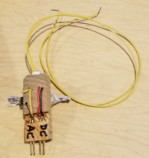


Ahhh, ok. The photo I remembered from a couple of years ago didn’t show the whole device, only the probe end. That’s why I thought it might be a battery. No matter, xfrmr is easier. And I have some button switches for other projects. It’s something I’m sure I can replicate. The difference of course is your boards come assembled, so I’ll have to do mine individually as I complete each one. Will work well I’m sure. Thx again for the help.
I was thinking of a test device something like this, but I was going to include a 0-100 milliammeter. Then when I find the light intensity I liked the best, I could quickly set each module to the same intensity (same milliamps) and thereby have all cars in the set at the same brightness level, at least in theory. I thought this might be kind of good because taking one or two cars apart again to adjust the light intensity after completion would be kind of a pita.
Rod
As long as you have the same number of similar LED's in each car, that will work. You don't actually need an LED in series with the meter, this is a constant current design, so you can just measure the current with a direct connection across the output.
Ted, the reason mine come assembled is it would take me a LONG time to hand solder a thousand modules! ![]()
gunrunnerjohn posted:Ted, the reason mine come assembled is it would take me a LONG time to hand solder a thousand modules!
Whoa! ![]()
![]()
Got a small question that I think I know the answer to. For grj's new board, I am thinking that since the center rail is the one carrying the DCS signal, the center rail pickups should be connected to pin 2 of the AC input (ie the round hole) since this connector runs through the 22 uH choke. Does that make sense?
Rod
GRJ's application is to test large batches whereas the rest of us would be testing much fewer. In case anyone missed it, what's neat about GRJ's tool are the spring-loaded test pins to make reliable contact to the 4 pads. These so-called "pogo pins" (like a kid's pogo stick) are not expensive but hard to imagine using them if assembling/testing just a handful of boards.
As GRJ states, the LED confirms capacitor operation. You see the brightness decay rather than going instantly dark. Note that GRJ mentions a high intensity LED that can presumably take the full current. So if using this for a 100mA board, use a suitable LED.
As for skipping the LED and hooking an ammeter directly across the board's output. A digital meter updates a few times per second so its numbers would jump making it tricky to see a smooth decay. An analog (needle) meter's spring slows the needle's return-to-zero and could be mis-interpreted as a smooth decay. Separately, if using a digital mA meter, most are fused when making mA-range measurements. Fuse values may be, say, 1/4 Amp or whatever. OTOH, using the 10 Amp setting may not give enough resolution when testing or calibrating the range of these low-current boards. So if the purpose of the mA metering is for test (before and as opposed to calibration), you may pop the mA fuse if there was an assembly error - fuse is replaceable but kind of a hassle.
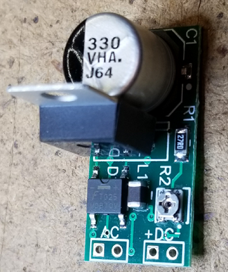
Here are a few pictures of the revised version of the PCB for my lighting project(s). These pictures were taken with my camera so they are a little better than the iPad pictures in the conversion thread.
Top and bottom of version 1.0.2.

Comparing length of this board to the original version.

Comparing width.

PCB populated with same components as original version. I will say it was more work to solder the components to the board this time as it was harder to hold everything in place and apply the heat and solder.

Even though it was harder to populate the PCB it does work. ![]()
![]()

I was a little concerned, but both connectors do fit on the revised PCB. However, I plan on using only one connector on the remaining boards. I will solder the supply wires directly to the PCB's AC IN pads along with a PTC to protect the wires. Since the PCB is attached to the floor of the cars' with double sided tape, one connector for the DC OUT wires will be sufficient to allow me to completely detach the roof if needed in the future. Paint the roofs white maybe?
Okay, breaks over, back to soldering. Well maybe later.
Edited*** I ended up using connectors for both the AC input and the DC output. Since I am using the original wiring from the wheel sets in the PE cars, it was just easier than trying to solder the wires directly to the board.


Rod Stewart posted:...For grj's new board, I am thinking that since the center rail is the one carrying the DCS signal, the center rail pickups should be connected to pin 2 of the AC input (ie the round hole) since this connector runs through the 22 uH choke. Does that make sense?
Doesn't matter. Choke performs same function either way.
Consider that the board works with 2-rail where DCS "hot" could be either rail depending on car orientation. ![]()
Access to this requires an OGR Forum Supporting Membership
