...and this one might be a "doozie".

Some of you might remember I started a thread last year (?) about obtaining and fixing a Varney Ten Wheeler. Many of you were most helpful with that project, and I'm happy to say it's still running nicely.

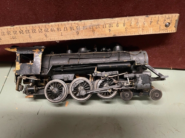
Never to leave well enough alone, I managed to pick up another example; this one is in pretty rough shape, but I didn't have to pay much, and I do love a challenge!

Here are a couple of photos (from the eBay listing) so you can get some idea of what I'm in for:

varnet 218213varney 82821varney 218212

Missing some parts, bent brass, this ought to be good!

Rest assured I'll be asking for some assistance, so remember that you have been warned...

Have a good weekend.

Mark in Oregon

Attachments

Images (3)
  • varnet 218213
  • varney 82821
  • varney 218212
Last edited by Strummer
Original Post

Replies sorted oldest to newest

Here's a question for you All Nation experts:

On my other Ten Wheeler, the motor is attached to the frame like so:

motor

On this example, the slightly smaller (5/8" stack) motor is mounted this way:

image000000-10 copy 2

You can see the (2) mounting brackets are in reverse order, with the L-shaped lower piece fore of the large upper piece. The motor is now 1/8" (the thickness of the upper bracket) closer to the front of the frame. It runs fine this way, but...

...now the boiler/cab can't seat itself down properly, as it comes into contact with the upper front of the motor!

I'm completely stumped; there's no other way for the motor to attach to the frame (and still keep the worm in alignment),  so what's a fellow to do?

I await your responses, comments and one-liners...

Mark in Oregon

Attachments

Images (2)
  • motor
  • image000000-10 copy 2

Jonathan

Thanks; although I'm not sure how much "progress I'm gonna make on this one...

Bob2

There is 2 11/16" between where the (2) screws pass through the base plate, up through the frame and into the mounting brackets. The front hole is where the worm end of the bracket is tightened; the rear hole is for the screw that holds down the motor end. I don't see any way to adjust any of that...and theoretically, I shouldn't have to, right?  My other example (with a slightly larger 1" motor) worked as designed...and those (2) holes are in exactly the same place.

I actually tried to move the lower bracket back up against the motor (like in my other one), but then the holes didn't line up for the rear mounting screw to pass through the base plate and up into the bracket.

In spite of the fact that these models can run really well (as my other example does), I'm not a big fan of the way these things were designed, what with the very rigid motor/bracket/coupling. There's no "play" in any of it, so you're kinda stuck with how it's laid out; unless I'm missing something...and I'm all ears...

Mark in Oregon
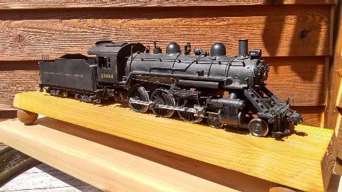
PS: there's currently an example on eBay and it's had a can motor installed. If someone on this Forum buys it, I would LOVE to see how that was done...

There is nothing to stop you from moving the motor aft.  Longer screws and spacers are all it takes.  You may have to lengthen the shaft between motor and worm, but that too is fairly trivial.  If it is a rigid straight shot, then a sleeve, soldered in place, is a ten minute exercise.  If it is two piece, a longer hose . . .

I will get wheels, rods, and screws underway in the next couple days.

@bob2 posted:

1. There is nothing to stop you from moving the motor aft.  Longer screws and spacers are all it takes.  You may have to lengthen the shaft between motor and worm, but that too is fairly trivial.  If it is a rigid straight shot, then a sleeve, soldered in place, is a ten minute exercise.  If it is two piece, a longer hose . . .

2. I will get wheels, rods, and screws underway in the next couple days.

1. I tried that: it put up a helluva vibration, so I figured that wasn't an option...

2. Thanks! I appreciate all your help...as always.

Mark in Oregon

Okay...I took a deep breath, and tried it again.

image000000-10

I used some more slot car spacers, and these bought me the 3/16" I needed to be able to get the boiler/cab on correctly; thank you "bob2" for the words of wisdom.

This is in much worse condition then I originally thought; have had to repair a lot of stuff and re-tap quite a few holes as many of the original screws were missing.

Good thing I enjoy doing this kind of stuff.........

Mark in Oregon

Attachments

Images (1)
  • image000000-10

Long before I became dangerous at the work bench I bagged the Atlantic variation of this by AN.  Noticed in a complete teardown was  VARNEY  cast into many of the zamac parts, hinting of its pedigree.  Without much revival work it returned to its stomping grounds on the Toronto Model Railroad Club layout.  They graciously gave it a successful test run on my request.  My initiation into 2 rail O and still in my hands.

Best of success with your revival progress.  Perhaps there's a post-war renaissance happinin' ?

Bruce

Add Reply

Post

OGR Publishing, Inc., 1310 Eastside Centre Ct, Suite 6, Mountain Home, AR 72653
800-980-OGRR (6477)
www.ogaugerr.com

×
×
×
×
Link copied to your clipboard.
×
×